Instruction Manual
D100310X012
667 Actuator (Size 30/30i - 76/76i and 87)
June 2017
23
19. The first four bolts tightened should be diametrically opposed and 90 degrees apart. Tighten these four bolts to 13
NSm (10 lbfSft).
20. Tighten the remaining bolts in a clockwise, criss‐cross pattern to 13 NSm (10 lbfSft).
21. Repeat this procedure by tightening four bolts, diametrically opposed and 90 degrees apart, to a torque of 27 NSm
(20 lbfSft).
22. Tighten the remaining bolts in a clockwise, criss‐cross pattern to 27 NSm (20 lbfSft).
23. After the last bolt is tightened to 27 NSm (20 lbfSft), all of the bolts should be tightened again to 27 NSm (20 lbfSft)
in a circular pattern around the bolt circle.
24. Once completed, no more tightening is recommended.
25. Return the actuator to service after completing the Loading Connection procedure in the Installation section and
the procedures in the Adjustments section.
Casing‐Mounted Travel Stops
Note
If repeated or daily manual operation is expected, the actuator should be equipped with a side‐mounted handwheel rather than a
casing‐mounted travel stop or top‐mounted handwheel. The side‐mounted handwheel is designed for more frequent use as
manual operator.
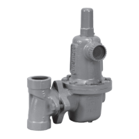
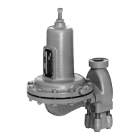
Casing‐mounted adjustable travel stops (shown in figures 21 through 25) are available to limit travel in the down
direction (extending the actuator stem) or in the up direction (retracting the actuator stem). The travel stop in figure
21 is a down travel stop, the travel stop in figure 22 is an up and down travel stop, and the travel stops in figures 23, 24,
and 25 are up travel stops.
Use the locknuts (key 151, figures 21 and 22), stem (key 150, figure 23), handwheel (key 58, figure 24) or cap screw
(key 177, figure 25) to set the point at which the travel stop limits travel. Be sure to tighten the locknuts and replace
the cap (key 149, figures 21 and 23; key 247, figure 22) after setting the travel stop.
Instructions are given below for disassembly and assembly. Perform the disassembly only as far as necessary to
accomplish the required maintenance; then, begin the assembly at the appropriate step.
Key numbers are shown in figures 21 through 25.
1. Remove the cap (key 149 or 247) if the travel stop uses one. For down travel stops, loosen the locknuts (key 151,
figures 21 and 22) so that the stop is not causing any spring compression.
2. Bypass the control valve, reduce loading pressure to atmospheric, and remove the tubing or piping from the
connection on top of the yoke (key 73, figures 6, 8, and 10).
3. For down travel stops, turn the spring adjuster (key 74, figures 6, 8, and 10) out of the yoke toward the stem
connector (key 31) to relieve all the compression in the spring (key 18).
4. For style 11 travel stops (figure 22), unscrew the cap screws (key 161), and make sure that the guide plate (key 157)
can turn between the handwheel body (key 148) and the mounting plate (key 158).
5. Use a wrench on the nuts (key 151) to unscrew the extension rod (key 150). Remove the rod, the handwheel body
(key 148), and the attached parts.
6. Unscrew the hex nuts and cap screws (keys 14 and 13, figures 6, 8, and 10) from the diaphragm casings. Lift off the
upper diaphragm casing (key 1, figures 6, 8, and 10) and, for the style 11 travel stop, the mounting plate (key 158).
For styles 10, 12 and 13, the travel stop assembly will be removed with the casing.
7. Note and record the position of travel stops (key 152) relative to the cap screws (key 154) for use in assembly.
Unscrew the travel stops and cap screws, and remove either the mounting plate (key 158) or the handwheel body
(key 148) and attached parts.

 Loading...