A regulator may vent some gas to
the atmosphere. In hazardous or
flammable gas service, vented gas may
accumulate and cause personal injury,
death or property damage due to fire or
explosion. Vent a regulator in hazardous
gas service to a remote, safe location
away from air intakes or any hazardous
area. The vent line or stack opening
must be protected against condensation
or clogging.
BeforeinstallingaType67C,67CR,67CS,67CSR,
67CF, 67CFR, 67CFS or 67CFSR regulator, be
sure the installation complies with the following
installation guidelines:
1. Regulator operation within ratings does not
preclude the possibility of damage from debris
in the lines or from external sources. Regulators
should be inspected for damage periodically and
after any overpressure condition.
2. Only personnel qualified through training and
experience should install, operate and maintain a
regulator.Makesurethatthereisnodamagetoor
foreign material in the regulator. Also ensure that
all tubing and piping is free of debris.
3. Install the regulator so that flow is from the IN to the
OUT connection as marked on the regulator body.
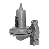
4. For best drainage, orient the drain valve (key 2) to
the lowest possible point on the dripwell (key 5). This
orientation may be improved by rotating the dripwell
with respect to the body (key 1).
5. A clogged spring case vent hole may cause the
regulator to function improperly. To keep this
vent hole from being plugged (and to keep the
spring case from collecting moisture, corrosive
Installation
Note
If the regulator is shipped mounted on
another unit, install that unit according
to the appropriate Instruction Manual.
!
WARNING
Personal injury, property damage,
equipment damage or leakage due to
escaping gas or bursting of pressure-
containing parts may result if this
regulator is overpressured or is installed
where service conditions could exceed
the limits given in the Specifications
section or where conditions exceed any
ratings of the adjacent piping or piping
connections. To avoid such injury or
damage, provide pressure-relieving or
pressure-limiting devices (as required
by the appropriate code, regulation or
standard) to prevent service conditions
from exceeding those limits.
The internal relief valve of the
Type 67CR, 67CSR, 67CFR or 67CFSR
does not provide full overpressure
protection. The internal relief valve is
designed for minor seat leakage only. If
maximum inlet pressure to the regulator
exceeds maximum pressure ratings of
the downstream equipment or exceeds
maximum allowable outlet pressure of
the regulator, additional overpressure
protection is required.
Table 1. Outlet Pressure Ranges and Control Spring Data
TYPE
OUTLET PRESSURE RANGES
CONTROL SPRING DATA
Color Material Part Number
Wire Diameter Free Length
psig bar In. mm In. mm
67C, 67CR,
67CF and 67CFR
0 to 20
0 to 35
0 to 60
0 to 125
0 to 1.4
0 to 2.4
0 to 4.1
0 to 8.6
Green stripe
Silver
Bluestripe
Red stripe
Music
Wire
GE07809T012
T14059T0012
T14058T0012
T14060T0012
0.135
0.156
0.170
0.207
3.43
3.96
4.32
5.26
1.43
1.43
1.43
1.43
36.2
36.2
36.2
36.2
0 to 35
0 to 60
0 to 125
0 to 2.4
0 to 4.1
0 to 8.6
Silver stripe
Blue
Red
Inconel
®
T14113T0012
T14114T0012
T14115T0012
0.156
0.172
0.207
3.96
4.37
5.26
1.43
1.43
1.43
36.2
36.2
36.2
67CS, 67CSR,
67CFS and 67CFSR
0 to 20
0 to 35
0 to 60
0 to 125
0 to 150
0 to 1.3
0 to 2.4
0 to 4.1
0 to 8.6
0 to 10.3
Green
Silver stripe
Blue
Red
Black
Inconel
®
10C1729X012
T14113T0012
T14114T0012
T14115T0012
10C1730X012
0.135
0.156
0.172
0.207
0.250
3.43
3.96
4.37
5.26
6.35
1.50
1.43
1.43
1.43
1.77
38.1
36.2
36.2
36.2
44.9
Inconel
®
isamarkownedbySpecialMetalsCorporation.
4
67C Series
 Loading...