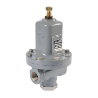
MR95 Series
Installation Guide
D103587X014
July 2017
Introduction
This Installation Guide provides instructions for installation, startup
and adjustment. To receive a copy of the Instruction Manual, contact
your local Sales Office or view a copy at www.fisher.com. For further
information refer to MR95 Series Instruction Manual, D103587X012.
PED Category
This product may be used as a safety accessory with pressure
equipment in the following Pressure Equipment Directive. It may
also be used outside of the Pressure Equipment Directive using
Sound Engineering Practice (SEP) per table below. For information
on the current PED revision see Bulletin: D103053X012.
TYPE PRODUCT SIZE BODY MATERIAL CATEGORY
MR95L/
MR95LD
1/4 NPT, DN 15 to 25 /
1/2 to 1 in.
All SEP
MR95H/
MR95HD
1/4 NPT, DN 15 to 25 /
1/2 to 1 in.
All SEP
DN 40 and 50 /
1-1/2 and 2 in.
Cast iron I
Steel and
Stainless steel
II
MR95HP/
MR95HT/
MR95HDP
1/4 NPT, DN 15 to 25 /
1/2 to 1 in.
All SEP
DN 40 and 50 /
1-1/2 and 2 in.
Steel and
Stainless steel
II
Specications
Available Constructions
Type MR95L: Pressure reducing regulator for outlet pressures
from 0.14 to 2.1 bar / 2 to 30 psig. 1/4 to 1 in. body sizes only.
Type MR95H: Pressure reducing regulator for outlet pressures
from 0.34 to 10.3 bar / 5 to 150 psig.
Type MR95HP: Pressure reducing regulator for outlet
pressures from 1.0 to 27.6 bar / 15 to 400 psig (soft-seated).
Type MR95HT: High temperature pressure reducing regulator
for outlet pressures from 1.0 to 20.7 bar / 15 to 300 psig
(metal seat) and up to 343°C / 650°F.
Type MR95LD: Pressure reducing differential regulator for
differential set pressures from 0.14 to 2.1 bar / 2 to 30 psi with
maximum inlet pressure up to 20.7 bar / 300 psi and maximum
outlet pressure up to 8.6 bar / 125 psi. 1/4 to 1 in. body
sizes only.
Type MR95HD: Pressure reducing differential regulator for
differential set pressures from 0.34 to 10.3 bar / 5 to 150 psi
with maximum inlet/outlet pressures up to 20.7 bar / 300 psig.
Type MR95HDP: Pressure reducing differential regulator for
differential set pressures from 0.34 to 10.3 bar / 5 to 150 psi
with maximum inlet/outlet pressures up to 41.4 bar / 600 psi.
Body and Orifice Sizes
1/4 NPT body: 7.22 mm / 0.284 in. orifice
DN 15 / 1/2 in. body: 10.56 mm / 0.416 in. orifice
DN 20 and 25 / 3/4 and 1 in. bodies: 16.02 mm / 0.631 in. orifice
DN 40 and 50 / 1-1/2 and 2 in. bodies (not available for
Types MR95L and MR95LD): 29 mm / 1.142 in. orifice
1. The pressure/temperature limits in this Installation Guide and any applicable standard or code limitation should not be exceeded.
2. The pressure limits given are based on the body size and body materials only. Actual pressure limits of the assembled regulator may decrease
and vary depending on the temperature, body end connection, diaphragm, seat and/or trim material of the regulator.
End Connection Styles
NPT, SWE, Welded and Integral CL150 RF, CL300 RF,
CL600 RF and PN 16/25/40 RF; all sizes are fabricated with
slip-on flanges (for welded end connections) and are EN
flanged 356 mm face-to-face (14 in. face-to-face)
Outlet and Differential Pressure Ranges
(1)
See Table 1
Maximum Spring Case Loading Pressure for
Types MR95LD, MR95HD and MR95HDP
See Table 2
Maximum Cold Working Pressures of
Body Size and Materials
(1)(2)
See Table 2
Pressure Registration
Internal or External
Maximum Temperature Ranges of
Diaphragm and Seat Materials
(1)(2)
See Table 3
Shutoff Classification Per ANSI/FCI 70-3-2004
Metal Seats: Class IV
PTFE: Class IV
Elastomer Seats: Class VI or better
API 614 Compliant
Steel or Stainless steel constructions with Stainless steel trim
meet API 614 Requirements.
Sour Gas Service Capability
Optional materials are available for applications handling sour
gases. These constructions comply with the recommendations
of NACE International Standards MR0175-2002 and MR0103.
Optional materials are available to meet ANSI/NACE
MR0175/ISO 15156.
Installation
!
WARNING
Only qualified personnel shall install or service
a regulator. Regulators should be installed,
operated and maintained in accordance with
international and applicable codes and regulations
and Emerson Process Management Regulator
Technologies, Inc. instructions.
If the regulator vents fluid or a leak develops in the
system, it indicates that service is required. Failure
to take the regulator out of service immediately
may create a hazardous condition.
Personal injury, equipment damage or leakage
due to escaping fluid or bursting of pressure
containing parts may result if this regulator
is overpressured or is installed where service
conditions could exceed the limits given in
the Specifications section or where conditions
exceed any ratings of the adjacent piping or
piping connections.