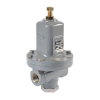
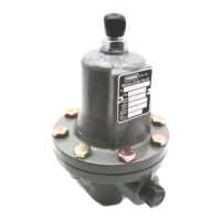
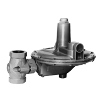
MR95 Series
5
Figure 2. MR95 Series Operational Schematics (continued)
CONTROL LINE TAP
*PRESSURE A MAY BE SUPPLIED BY ANOTHER PRESSURE SYSTEM OR A MANUAL LOADING REGULATOR.
DIAPHRAGM
STEM
ORIFICE
VALVE PLUG
FRONT AND INTERNAL VIEW OF
TYPE MR95HD WITH INTERNAL PRESSURE REGISTRATION
BACK VIEW OF
TYPE MR95HD WITH EXTERNAL PRESSURE REGISTRATION
Type 95HD Differential Pressure Reducing Regulator
M1006
OUTLET PRESSURE
LOADING PRESSURE
October 2006
Type 95HD
INLET PRESSURE
LOADING PRESSURE
INLET PRESSURE
OUTLET PRESSURE
CONTROL SPRING
HANDWHEEL
PITOT TUBE
PRESSURE A*
(SPRING CASE
LOADING
PRESSURE)
PRESSURE A +
SPRING SETTING =
PRESSURE B
PRESSURE B
(OUTLET
PRESSURE)
For Types MR95LD and MR95HD
Differential Pressure Regulators
Types MR95LD and MR95HD regulators maintain
a differential pressure between the loading supply
pressure and the downstream pressure of the regulator.
See Figure 2. The design of the regulator isolates the
diaphragm and pressure response chamber from the
main ow stream. The downstream pressure (outlet
pressure) is registered under the diaphragm through
the pitot tube or registration hole. If the downstream
pressure increases, pressure under the diaphragm
also increases. This force overcomes the spring
compression and loading supply pressure, allowing the
stem to rise. The valve plug spring forces the valve
plug closer to the orice. Flow through the regulator
is reduced so that downstream pressure returns to
the desired differential level. When the downstream
pressure decreases, the opposite action takes place.
Pressure under the diaphragm decreases. The valve
stem pushes the valve plug downward, opening the
ow stream and increasing the uid ow through the
regulator. Downstream pressure rises back to the
desired differential level.

 Loading...


