Y600A Series
2
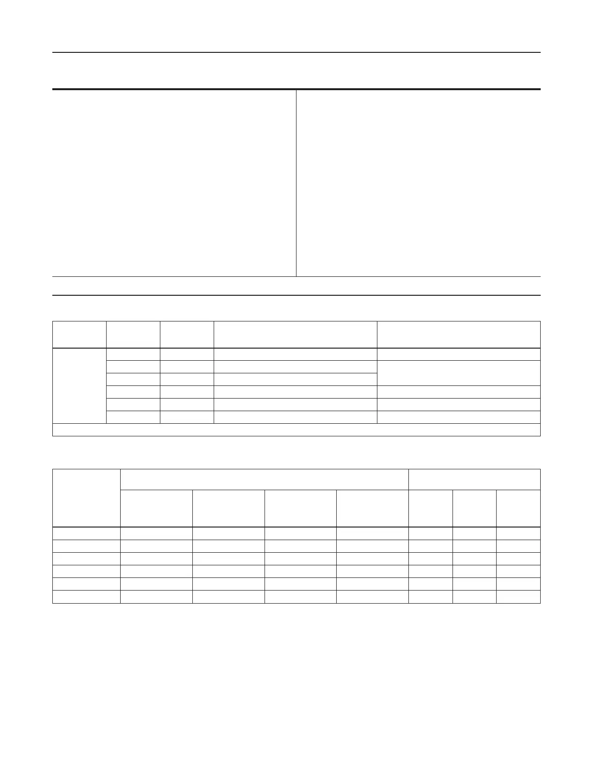
Body Sizes (Inlet x Outlet) and End
Connection Style
(1)
3/4 x 3/4 or 1 x 1-inch NPT
Maximum Inlet Pressure (Body Rating)
(2)
150 psig (10,3 bar)
Maximum Outlet Pressure (Casing)
(2)
20 psig (1,38 bar)
Maximum Operating Inlet Pressure
See Table 2
Maximum Operating Outlet Pressure to Avoid Internal
Parts Damage
(2)
2 psig (0,14 bar) above outlet pressure setting
Specications
Outlet Pressure Ranges
(2)
See Table 1
Flow Coecients
See Table 2
Temperature Capabilities
(2)
–20° to 180°F (–29° to 82°C)
Spring Case Vent Connection
1/4-inch NPT
Diaphragm Case Connection
1/2-inch NPT
Approximate Weight
13 pounds (5,9 kg)
1. End connections for other than U.S. standards can usually be provided; consult your local Sales Ofce.
2. The pressure/temperature limits in this instruction manual and any applicable standard or code limitation should not be exceeded.
Table 1. Outlet (Control) Pressure Ranges
TYPE
NUMBER
SPRING
COLOR
SPRING PART
NUMBER
OUTLET PRESSURE RANGE WITH
SPRING CASE ABOVE DIAPHRAGM
(1)
APPROXIMATE POINT ABOVE PRESSURE
SETTING AT WHICH THE TYPE Y600AR
INTERNAL RELIEF STARTS TO DISCHARGE
Y600A,
Y600AM,
Y600AR
Red 1B653827052 4 to 8-inches w.c. (10 to 20 mbar) 10 to 24-inches w.c. (25 to 60 mbar)
Olive drab 1B653927022 7 to 16-inches w.c. (17 to 40 mbar)
10 to 26-inches w.c. (25 to 65 mbar)
Yellow 1B537027052 15-inches w.c. to 1.2 psig (37 to 83 mbar)
Light green 1B537127022 1.2 to 2.5 psig (0,08 to 0,17 bar) 0.5 to 2 psig (0,03 to 0,14 bar)
Light blue 1B537227022 2.5 to 4.5 psig (0,17 to 0,31 bar) 0.5 to 3 psig (0,03 to 0,21 bar)
Black 1B537327052 4.5 to 7 psig (0,31 to 0,48 bar) 1 to 4 psig (0,07 to 0,28 bar)
1. Minimum outlet pressure setting may be approximately 1-inch w.c. (2 mbar) lower if spring case is below diaphragm.
Note
If the regulator is shipped mounted on
another unit, install that unit according to
the appropriate instruction manual.
1. Only personnel qualied through training and
experience should install, operate, and maintain a
regulator. For a regulator that is shipped separately,
make sure that there is no damage to, or foreign
material in the regulator. Also ensure that all tubing
and piping are free of debris.
Table 2. Maximum Operating Inlet Pressures
ORIFICE SIZE,
INCHES (mm)
MAXIMUM OPERATING INLET PRESSURE, PSIG (bar)
WIDE-OPEN FLOW COEFFICIENTS
FOR EXTERNAL RELIEF SIZING
With 1.2 PSIG
(0,08 bar) or Less
Outlet Pressure
Setting
With 1.2 to 2.5 PSIG
(0,08 to 0,17 bar)
Outlet Pressure
Setting
With 2.5 to 4.5 PSIG
(0,17 to 0,31 bar)
Outlet Pressure
Setting
With 4.5 to 7 PSIG
(0,31 to 0,48 bar)
Outlet Pressure
Setting
C
g
C
v
C
1
1/8 (3,17) 150 (10,3) 150 (10,3) 150 (10,3) 150 (10,3) 12.3 0.35 35
3/16 (4,76) 150 (10,3) 150 (10,3) 150 (10,3) 150 (10,3) 27.6 0.79 35
1/4 (6,35) 75 (5,17) 150 (10,3) 150 (10,3) 150 (10,3) 50 1.43 35
3/8 (9,53) 35 (2,41) 60 (4,14) 60 (4,14) 60 (4,14) 110 3.14 35
1/2 (12,7) 8 (0,55) 10 (0,69) 12 (0,83) 12 (0,83) 200 5.71 35
9/16 (14,3) 5 (0,34) 6 (0,41) 8 (0,55) 8 (0,55) 250 7.14 35
 Loading...


