Y600A Series
4
Body Area
This procedure is for gaining access to the disk assembly,
orice, body O-ring, and pitot tube if used. All pressure
must be released from the diaphragm casing, and the
disk assembly must be open, before these steps can
be performed.
1. Remove the cap screws (key 2) and separate the
diaphragm casing (key 4) from the body (key 1).
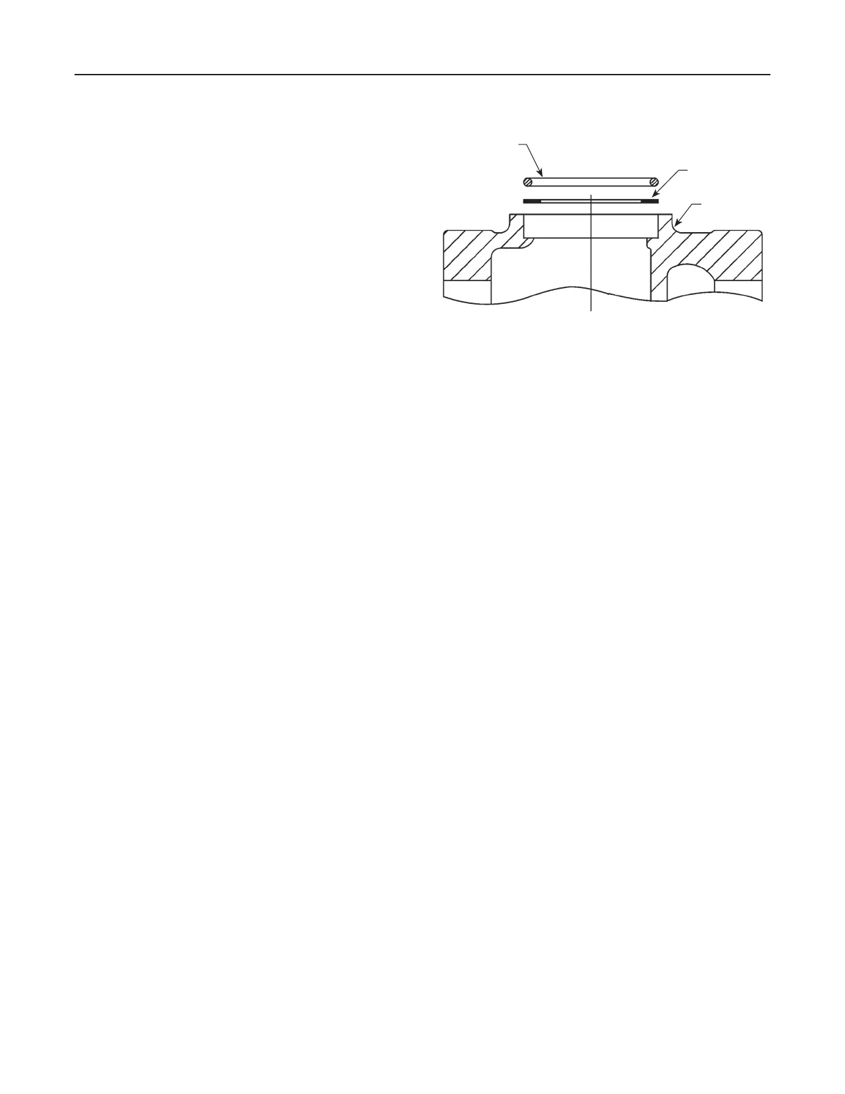
2. Remove and inspect the body seal O-ring (key 11) and
the backup ring (key 48). See Figure 2.
3. Inspect and replace the orice (key 5) if necessary.
Protect the orice seating surface during disassembly
and assembly. Lubricate the threads of the
replacement orice with a good grade of light grease
and install with 29 to 37 foot-pounds (39 to 50 N•m)
of torque.
4. To replace the disk assembly (key 13), remove the
cotter pin (key 15). If not necessary, skip to step 7.
5. To replace the pitot tube (key 32, Figures 3 and 6) on
the Types Y600A and Y600AR, remove the machine
screws (key 33), install the new pitot tube, and secure
with the machine screws. Position the pitot tube so
that it points into the outlet of the body (key 1) by
rotating the guide insert (key 18).
6. Install the disk assembly (key 13) and secure it with
the cotter pin (key 15).
7. Place backup ring (key 48) into the body (key 1).
Then place the body seal O-ring (key 11) into the
body. See Figure 2.
8. Place the diaphragm casing (key 4) on the body
(key 1). Secure the the diaphragm casing to the body
with the cap screws (key 2) using 7 to 9 foot-pounds
(9 to 12 N•m).
Diaphragm and Spring Case Area
This procedure is for gaining access to the spring,
diaphragm, lever assembly stem, and Type Y600AM
stem O-ring. All pressure must be released from the
diaphragm casing before performing these steps.
Note
Any Type 662 remote control drive unit
used with a Y600A Series regulator must
be removed from the spring case (key 3)
before these steps can be performed.
1. Remove the closing cap (key 22), and turn the
adjusting screw (key 35) counterclockwise to remove
the compression from the spring (key 6).
2. If the only maintenance is to change the control
spring, take out the control spring and replace with
the desired spring. Turn the adjusting screw (key 35)
clockwise to compress the spring to the desired outlet
pressure setting. Skip to step 11.
3. If further maintenance to the internal diaphragm
casing parts is required, remove the hex nuts (key 23,
not shown) and cap screws (key 24). Remove the
diaphragm (key 10) plus attached parts by tilting
them so that the pusher post (key 8) slips off the lever
assembly (key 16). To separate the diaphragm from
the attached parts, unscrew the cap screw (key 38,
Figures 3 and 4) from the pusher post (key 8)
for a Type Y600A or Y600AM, or unscrew the relief
valve spring holder (key 37, Figure 6) from the pusher
post (key 8) for a Type Y600AR. If the only further
maintenance is to replace the diaphragm parts, skip
to step 7.
4. To replace the lever assembly (key 16), remove the
machine screws (key 17). To replace the stem
(key 14) or the Type Y600AM stem O-ring (key 30,
Figure 4), also perform Body Area Maintenance
procedure steps 1 and 4, and pull the stem (key 14)
out of the diaphragm casing (key 4). With a Type
Y600AM, grease the replacement stem O-ring
(key 30, Figure 4) with a good grade of lubricant and
install it on the tem (key 14).
5. Install the stem (key 14) into the diaphragm casing
(key 4) and perform Body Area Maintenance
procedure steps 6 through 8 as necessary.
Figure 2. Expanded View of the Body Area Showing
the Body Seal O-ring and Backup Ring Placement
BODY SEAL
O-RING (KEY 11)
BACKUP RING
(KEY 48)
BODY (KEY 1)
 Loading...


