The PACSystems RX3i PROFINET Controller, model IC695PNC001, is a module designed to connect a PACSystems RX3i controller to a high-speed PROFINET local area network (LAN). Its primary function is to enable the RX3i controller to communicate with I/O devices on the LAN. The PNC001 is certified as a PROFINET I/O Version 2.2 I/O Controller, supporting both 100 Mbps and 1 Gbps operation.
Function Description:
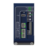
The IC695PNC001 acts as a PROFINET I/O Controller, facilitating communication between the RX3i CPU and various I/O devices over a PROFINET network. It supports full configuration services for the RX3i PROFINET Controller and connected Emerson and third-party I/O devices using PAC Machine Edition (PME). The module is designed for use in star, ring, and daisy-chain/line network topologies. It features four switched Ethernet ports: two 8-conductor RJ-45 shielded twisted pair 10/100/1000 Mbps copper interfaces and two Small Form-factor Pluggable (SFP) cages for user-supplied SFP devices. The internal clock of the PNC001 is synchronized with the RX3i CPU, allowing for time-stamped diagnostic entries.
Important Technical Specifications:
- PROFINET Support: PROFINET Version 2.2 General Class A I/O-Controller. Supports redundantly controlled operation conforming to PROFINET V2.3 Type S-2 System Redundancy.
- Power Requirements:
- PNC001-Ax: 3.3 Vdc: 0.6 A (no SFP devices), 1.3 A maximum (two SFP devices installed, 0.35 A per SFP device); 5 Vdc: 1.5 A maximum.
- PNC001-Bxxx: 3.3 Vdc: 0.5 A (no SFP devices), 1.2 A maximum (two SFP devices installed, 0.35 A per SFP device); 5 Vdc: 0.75 A maximum.
- Operating Temperature Range:
- PNC001-Ax: 0°C to 60°C.
- PNC001-Bxxx: -25°C to 60°C.
- Maximum surrounding air temperature without a fan.
- Port Connectors: Two RJ-45 and two SFP Cages (SFP devices not included, available separately).
- Micro USB Connector: One, for communication with a computer using Command Line Interface (only on -Ax version).
- LAN: IEEE 802.2 Logical Link Control Class I, IEEE 802.3 CSMA/CD Medium Access Control 10/100/1000 Mbps. PROFINET communications require 100 and 1000 Mbps link speed; 10 Mbps can be used for other Ethernet traffic.
- Maximum I/O Memory: 128 Kbytes of combined input/output memory per PROFINET Controller.
- CPU Status Bits: 32.
- PROFINET I/O Device Data Update Rates: Configurable: 1 ms, 2 ms, 4 ms, 8 ms, 16 ms, 32 ms, 64 ms, 128 ms, 256 ms, and 512 ms.
- Number of IP addresses: One.
- Number of MAC Addresses: Five (one per external port and one internal).
- Hot-swappable: Yes.
- System Maximum Limits:
- PNCs per RX3i CPU: Four (must be in the main rack, not remote).
- I/O-Devices per I/O-Controller: 128 (limited to 63 MRP Clients if configured as an MRP Manager).
- I/O-Devices per Network: 255 (spread across up to 8 IO-Controllers).
- I/O-Devices per RX3i CPU: 255 (spread across up to 4 PROFINET Controllers).
- I/O-Controllers per network: 8.
- Number of PROFINET Slots per device: 256.
- Number of PROFINET Subslots per slot: 256.
- Number of PROFINET Submodules per RX3i CPU: 2048.
- Number of I/O-Controllers (Programmer Limits): 128 (32 RX3i CPU targets × 4 IO-Controllers per RX3i CPU).
- Number of I/O-Devices (Programmer Limits): 4080 (255 per network × 16 PROFINET networks).
- Total number of devices (Programmer Limits): 4208 (excluding backplanes, power supplies, or I/O modules).
- EMC Compliance: To meet EN 55011 and FCC Class A radiated emissions, the control system must be mounted in a metal enclosure when three or more IC695PNC001 modules are used. All enclosure surfaces must be adequately grounded, and external wiring routed in metal conduit.
- Hazardous Area Use: Suitable for use in Class I, Division 2, Groups A, B, C, and D Hazardous Locations, or non-hazardous locations only. ATEX Zone 2 certified for use in Zone 2, Group IIC, and rated IP54, requiring mounting in a certified enclosure accessible only with a tool.
Usage Features:
- Firmware Upgrades: Supported via WinLoader software utility (if host CPU has a serial port) or a Web-based tool (if host CPU has no serial port).
- Restart Pushbutton: Allows manual restart of the PNC001 without power cycling the system.
- LED Indicators: Includes OK, LAN, STATUS, CONFIG, ACTIVE, and Port LEDs to provide visual status of the module's health, network activity, configuration, and PROFINET connections. The -Ax version includes a USB LED, while the -Bxxx version does not. Port LEDs indicate link speed, connection, and activity.
- Hot-Swap Capability: The PNC001 supports insertion/removal while power is applied to the system.
- SFP Devices: Supports various SFP types for fiber optic connections, including 10/100/1000 Mbps Copper, 100/1000 Mbps Multi-mode Fiber, and 100/1000 Mbps Single-mode Fiber. Optical SFPs use invisible lasers, so ports should remain covered when not in use.
- Media Redundancy Protocol (MRP): The module supports MRP, allowing for redundant network configurations. Users are cautioned not to close the network ring until the MRP configuration with a Media Redundancy Manager (MRM) is downloaded to prevent continuous packet cycling.
- Single Fiber Break Detection: The IC695PNC001-Bxxx PROFINET Controller and IC695PNS001-Bxxx/IC695PNS101 PROFINET Scanners can detect a ring break on a single fiber of the network fiber pair on a fiber SFP. This feature requires specific firmware versions.
- HART Pass-Through: Supported with specific firmware versions and a HART-capable PROFINET scanner.
Maintenance Features:
- Status Reporting: The PNC001 provides 32 bits of status information to the RX3i CPU's reference memory, including module health, port connection status, SFP health, and overall device connection status. This allows for detailed diagnostics and troubleshooting.
- Module OK (Bit 1): Indicates if the module is functioning properly (1) or powering up/failed (0).
- Port Link Up (Bits 2-5): Indicates if a port is connected and operating correctly (1) or not connected/error/empty SFP cage (0).
- Port SFP OK (Bits 7-8): Indicates if the SFP matches configuration and is operational (1) or not (0).
- All Devices Connected (Bit 9): Indicates if all configured devices are connected and communicating over PROFINET (1) or not (0).
- MRP Enabled (Bit 11): Indicates if MRP is enabled (1) or not (0).
- MRP Role (Bit 12): Indicates if the PNC001 is an MRP client (0) or MRP Manager (1) when MRP is enabled.
- MRP Ring Status (Bit 13): Indicates if the ring is open (0) or closed (1) when MRP is enabled and the PNC001 is the MRM.
- ESD Protection: Personnel must discharge any electrostatic charge using a grounded ESD strap or other means when installing, operating, or maintaining the IC695PNC001.
- SFP Device Handling: When operating temperatures are high (above 40°C for the PNC001, potentially over 70°C for SFPs), protective gloves or tools (needle-nose pliers) should be used to remove hot SFP devices.
- Configuration Management: The PNC001 restores data from internal non-volatile memory upon power-up. If the RX3i CPU has configuration data for the PROFINET Controller, it re-delivers this data, superseding previously stored parameters.
- Diagnostic Tools: The PAC Machine Edition (PME) is the primary tool for configuring the PROFINET network. The PROFINET DCP tool (available in PME) can be used for device discovery, but requires administrator privileges for full functionality.
- Monitoring Remote I/O Device Availability: Applications should monitor the Controller's "All Devices Connected" status bit, use the PNIO_DEV_COMM function block, or check the CPU's I/O Fault Table for "Loss of Device" faults to track remote I/O device availability. Individual I/O modules can be monitored by enabling point faults or looping critical points to an input module.