Do you have a question about the Emerson iPro and is the answer not in the manual?
Details capabilities of the iPro Case Controller, including managing evaporators, communication, and load control.
Lists part numbers for the iPro Case Controller and related accessories for ordering.
Provides dimensions and mounting guidelines for the iPro Case Controller, XEV20D, and IPX106D using DIN rail.
Details the iPro Case Controller's microprocessor, I/O capabilities, and communication ports.
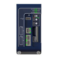
Provides a detailed description of each connector and its function on the iPro Case Controller.
Describes the Visograph 2.0 V2IPG as the local user interface for the iPro Case Controller.
Details the IPX106D as an input/output expansion board for the iPro Case Controller.
Describes the XEV20D as a stepper valve actuator for electronic expansion valves.
Details valve wiring connections for XEV20D, including bipolar and unipolar valve types.
Outlines maximum current values the XEV20D can supply to stepper valves.
Explains the CAN bus protocol for communication between iPro and XEV20D devices.
Specifies transformer requirements for iPro, XEV20D, and IPX, emphasizing dedicated transformers.
Details recommended wire types and maximum distances for power wiring to devices.
Provides Emerson wiring guidelines for analog sensors, RS485, pressure transducers, and stepper valves.
Instructions on how to power the iPro Case Controller using a 24VAC transformer.
Details the 24VAC power supply requirements for the XEV20D valve actuator.
Explains the 24VAC power supply requirements for the IPX106D expansion module.
Describes the wiring connection for the Visograph display to the iPro remote display port.
Details the 10 analog inputs on the iPro, including power supply and common connections.
Explains the 4 analog inputs on the XEV20D, including power supply and common connections.
Describes the 7 analog inputs on the IPX106D expansion module.
Details the 20 opto-insulated digital inputs on the iPro, including configuration and notes.
Describes the 3 digital inputs on the IPX106D, including input type and notes.
Details the 15 digital outputs (relays) on the iPro, including type, load, and notes.
Describes the 6 digital outputs (relays) on the IPX106D, including type, load, and notes.
Details the 6 opto-insulated analog outputs on the iPro, including power and load.
Describes the 3 analog outputs on the IPX106D expansion module, including power and load.
Explains temperature modes like Low, Med, and Dual Temp, and setpoint switching.
Details the common superheat setpoint parameter (SupHtSet) for EEV control loops.
Describes the five available control modes for refrigeration systems.
Manages case temperature and superheat, controlling the refrigeration relay.
Controls superheat for EEVs using PID loops and suction pressure/temperature.
Manages temperature control and EEPR valve regulation for case lineups.
Manages EEPR, LLSV, and up to three EEVs for a case lineup.
Covers defrost initiation, master/slave operation, relay control, and valve positioning.
Details internal scheduling for controlling case lights.
Describes fan operation modes based on the Fop parameter.
Details monitoring fan motor RMS current using an external transducer.
Describes how the controller can be enabled or disabled via digital input, E2E, or Visograph.
Defines parameters for managing expansion valves (EEVs) and EEPR valve presence and position.
Details automatic and manual calibration procedures for EEV and EEPR valves.
Step-by-step guide to calibrating electronic valves using the Visograph interface.
Specifies the recommended shielded twisted pair cable for BACnet MS/TP wiring.
Details the daisy chain topology requirement for BACnet MS/TP connections.
Guides on setting BACnet MAC address, Device ID, APDU timeout, and Max Master.
Specifies the recommended shielded twisted pair cable for MODBUS network wiring.
Details the daisy chain topology requirement for MODBUS network connections.
Explains how to set unique MODBUS addresses and baud rates for master and slave controllers.
Guides on configuring slave controller addresses within the master controller's menu.
Shows how to view temperature input values using the Visograph's case tab.
Explains how to view valve positions and superheat data via the Visograph valve overview tab.
Instructions on how to enter the Visograph Main Menu by holding the T4 key.
Guides on configuring digital and analog inputs/outputs via the Visograph.
Details configuring digital inputs, including polarity settings.
Details configuring digital outputs (relays) and their polarity.
Allows temporary override of system relay outputs and electronic valves.
Guides for verifying sensor, input, output, and valve operation before shipping.
Configures the E2E controller's COM port for BACnet MS/TP communication.
Sets up E2E BACnet network parameters like DevId, MAC address, and baud rate.
Steps to add and connect iPro Case Controllers within the E2E system.
Guides on scanning for and commissioning iPro devices within the E2E system.
Lists parameters related to fan operation mode and activation after defrost.
Details parameters for setting temperature alarms, hysteresis, and delays.
Lists parameters for configuring analog inputs like probes and current transducers.
Provides a comprehensive wiring diagram for the iPro Case Controller system.
| Brand | Emerson |
|---|---|
| Model | iPro |
| Category | Controller |
| Language | English |