Detailed Description of Connectors for the iPro Case Controller Overview • 7
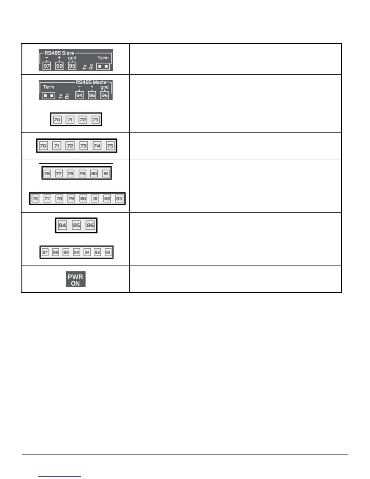
RS485 Slave port is used to connect the Master and Slave Case Controllers Rx and Tx
LED to indicate that communication is active.
Closed circuit terminal (Term)
RS485 Master port is used to connect iPro Case Controller and Master Supervisory
Controller
Rx and Tx LED to indicate that communication is active Closed circuit terminal
(Term)
Digital relay outputs (for digital outputs with voltage-free contacts) three (3) NO
relays, one (1) common
Digital relay outputs (for digital outputs with live contacts) three (3) NO relays, one (1)
common and two (2) voltage free (Neutral)
Digital relay outputs (for digital outputs with voltage-free contacts) five (5) NO relays,
one (1) common
Digital relay outputs (for digital outputs with live contacts) five (5) NO relays, one (1)
common and two (2) voltage free (Neutral)
Digital relay outputs
two (2) NO relays, one (1) common
Digital relay outputs (only for 215D versions)
five (5) NO relays, one (1) common and one (1) voltage free (Neutral)
Green LED to indicate the presence of power
Table 4-2 - iPro Connections and Descriptions