iPro Digital Outputs Wiring Digital Outputs • 21
8 Wiring Digital Outputs
8.1. iPro Digital Outputs
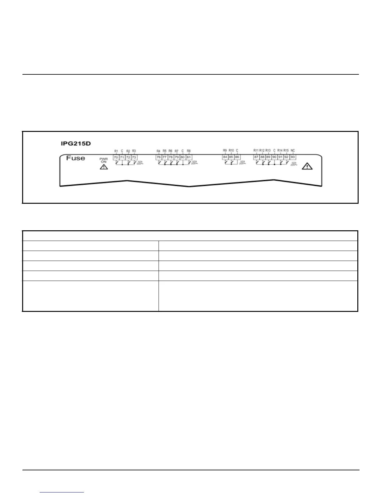
The 15 digital outputs are located across four (4) separate connectors across the top side of the iPro Case Controller. The normally open
outputs on each connector share the same common and are not fused. Make sure to use the same voltage for all loads connected to these
relays; do not mix voltages.
Figure 8-1 - iPro Digital Output Wiring
DIGITAL OUTPUTS
TYPE: Relays with NO contacts
NUMBER OF OUTPUTS: 15
TYPE OF OUTPUT: Relays with normally open contact
MAXIMUM LOAD: 5A (250 VAC) SPST 5(2)A
NOTES: Verify the capacity of the output used. There is double insulation
between the digital outputs and the low voltage of the rest of the circuit.
Do not use different voltages for the various groups of relays or within
each group.
Table 8-1 - iPro Digital Output Specifications