General Description/ Introduction • 1
1 General Description/ Introduction
The iPro Case Controller is a microprocessor-based controller for use in controlling temperature and Superheat in refrigerated fixtures
and walk-in boxes. The controller is suitable for medium and low temperature applications and can control all loads in a refrigerated box
or fixture. These include lighting, fans, defrost heaters, and solenoid valves. The iPro Case Controller system
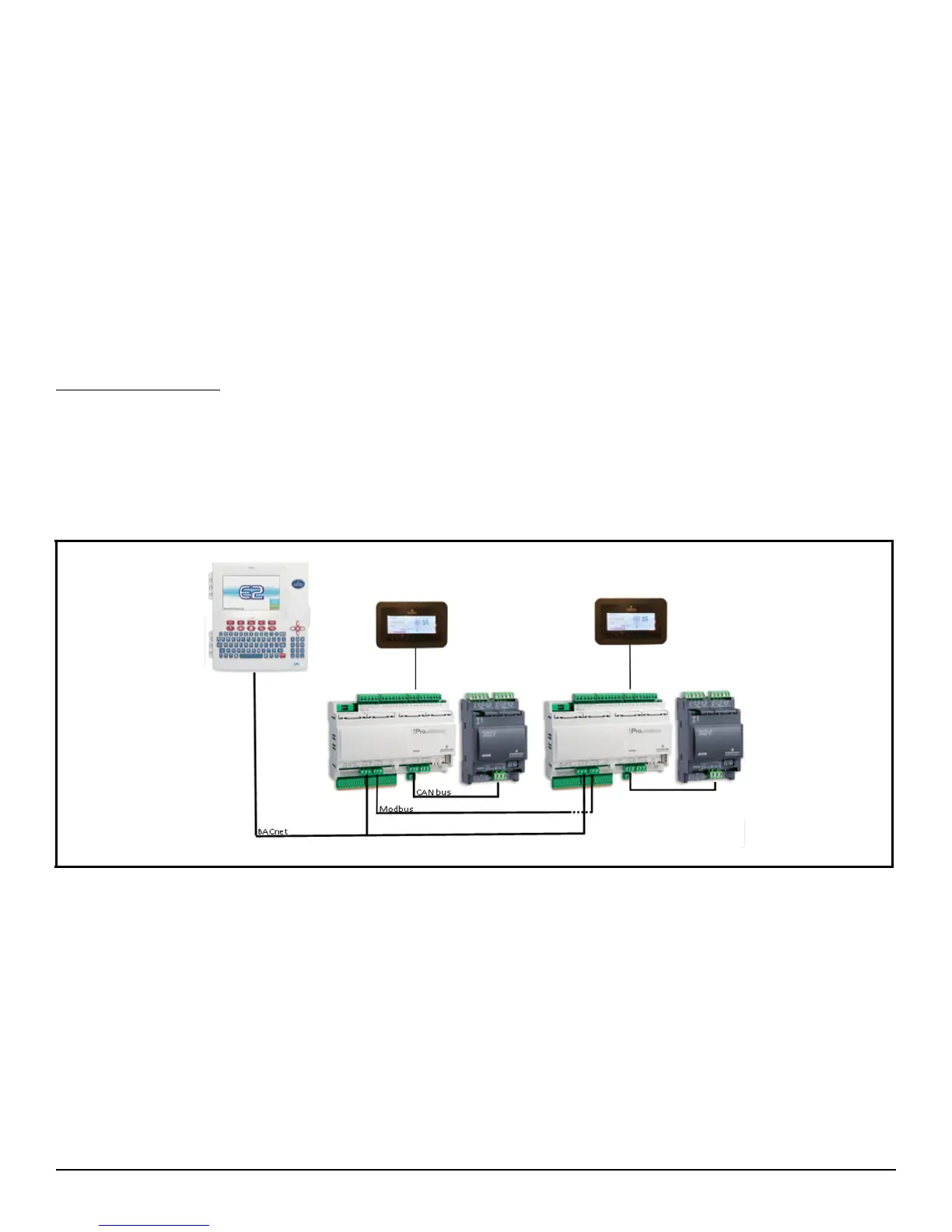
is comprised of at least one iPro Case Controller and one to two XEV20D valve drivers depending on the installation. There is also an
input/output expansion module supported by the software that can be used if needed, although typically the I/O available on the iPro
Case Controller is adequate for most installations. When more than one case or fixture is used within the refrigeration circuit, the iPro
Case Controller can communicate critical information between case controller devices via Modbus from device to device. The controller
can be integrated into an EMS system controller via Modbus or BACnet MS/TP/IP and is currently integrated into the Emerson E2E
rack controller using BACnet MS/TP or IP. The controller can also be configured to run completely standalone, controlling the
refrigeration system with no commands sent from E2E or a higher-level EMS controller.
Overview of Capabilities
• Each case controller can manage control of up to three evaporators Superheat in one case with associated temperature sensors,
transducers and electronic valves.
• One master case controller can communicate with up to five (5) slave case controllers within each refrigeration circuit, six (6)
case lineup is the maximum configuration.
• Control one (1) EEPR for the refrigeration circuit lineup.
• Manages all loads in a refrigerated case: lighting, fans, defrost heaters, and solenoid valves.
Figure 1-1 - System Layout