12 • iPro Case Controller I&O Manual FM V1.01 026-1738 Rev 1
4.6. XEV20D Valve Connections
The wires from the valve wiring harness should be terminated at the XEV20 connectors labeled valve 1 and valve 2. See Table 4-6 and
Table 4-7 below for terminal numbers associated with each valve wire color.
LED MODE MEANING
PWR ON On Tells that the model is powered correctly
ALARM On Tells that an alarm is present
TX/RX Blinking CAN Bus or LAN activity, communication activated
TX/RX On No link
OPEN V1 Blinking Valve 1 is opening
OPEN V1 On Valve 1 is completely opened
CLOSE V1 Blinking Valve 1 is closing
CLOSE V1 On Valve 1 is completely closed
OPEN V2 Blinking Valve 2 is opening
OPEN V2 On Valve 2 is completely opened
CLOSE V2 Blinking Valve 2 is closing
CLOSE V2 On Valve 2 is completely closed
Table 4-5 - XEV20D LED Functions
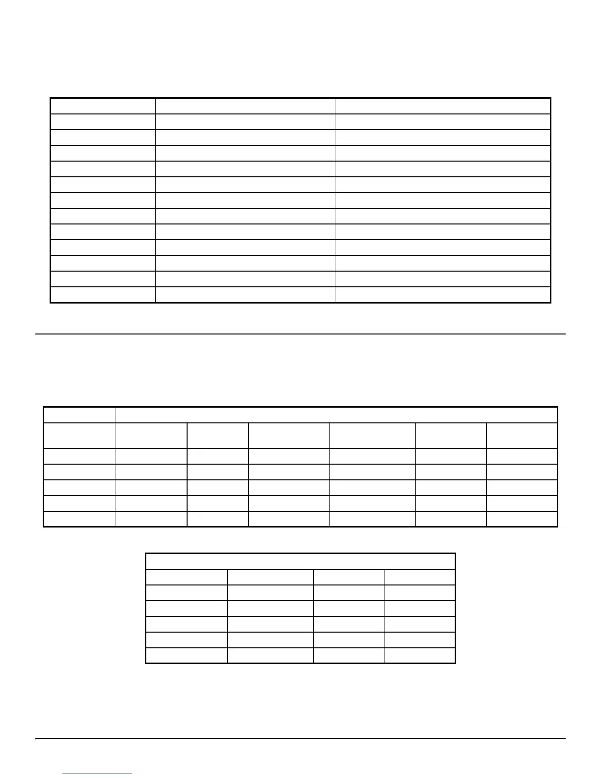
4 Wire Valves (Bipolar)
Terminal
Numbers
Alco EX Alco EX5/6 Sporlan SEI-SHE Sporlan CDS4-17 Danfoss ETS Carel E2V-E7V
1 GREEN WHITE GREEN GREEN GREEN GREEN
2 BROWN BLACK RED RED RED YELLOW
3 YELLOW BROWN BLACK BLACK WHITE BROWN
4 WHITE BLUE WHITE WHITE BLACK WHITE
5 - Common N/A N/A N/A N/A N/A N/A
Table 4-6 - Bipolar Valve Connections
5-6 Wire Valves (Unipolar)
Terminal Numbers Spolar Saginomiya EX3
1 BLACK BLACK BLUE
2 YELLOW YELLOW BLACK
3 RED RED BROWN
4 ORANGE ORANGE WHITE
5 - Common GRAY GRAY GRAY
Table 4-7 - Unipolar Bipolar Valve Connections