6 • iPro Case Controller I&O Manual FM V1.01 026-1738 Rev 1
4.2. Detailed Description of Connectors for the iPro Case Controller
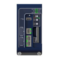
LEGEND
1 GENERAL STATUS LED 8 RS485 SLAVE PLUG-SLAVE CONTROLLER NETWORK
2 RELAY OUTPUT CONNECTORS 9 ANALOG INPUTS/24VAC POWER IN CONNECTOR
3 LED 1 AND GENERAL ALARM LED 10 CAN BUS CONNECTION-FOR XEV20D&IPX MODULE
4 RS485 TRANSMIT/RECEIVE LED 11 REMOTE DISPLAY PORT-VISOGRAPH
5 DIGTIAL INPUT CONNECTOR 12 TCP/IP PORT-BACNET IP PORT
6 BACNET MS/TP CONNECTION 13 USB PORT
7 ANALOG OUTPUT CONNECTOR
Table 4-1 - iPro Hardware
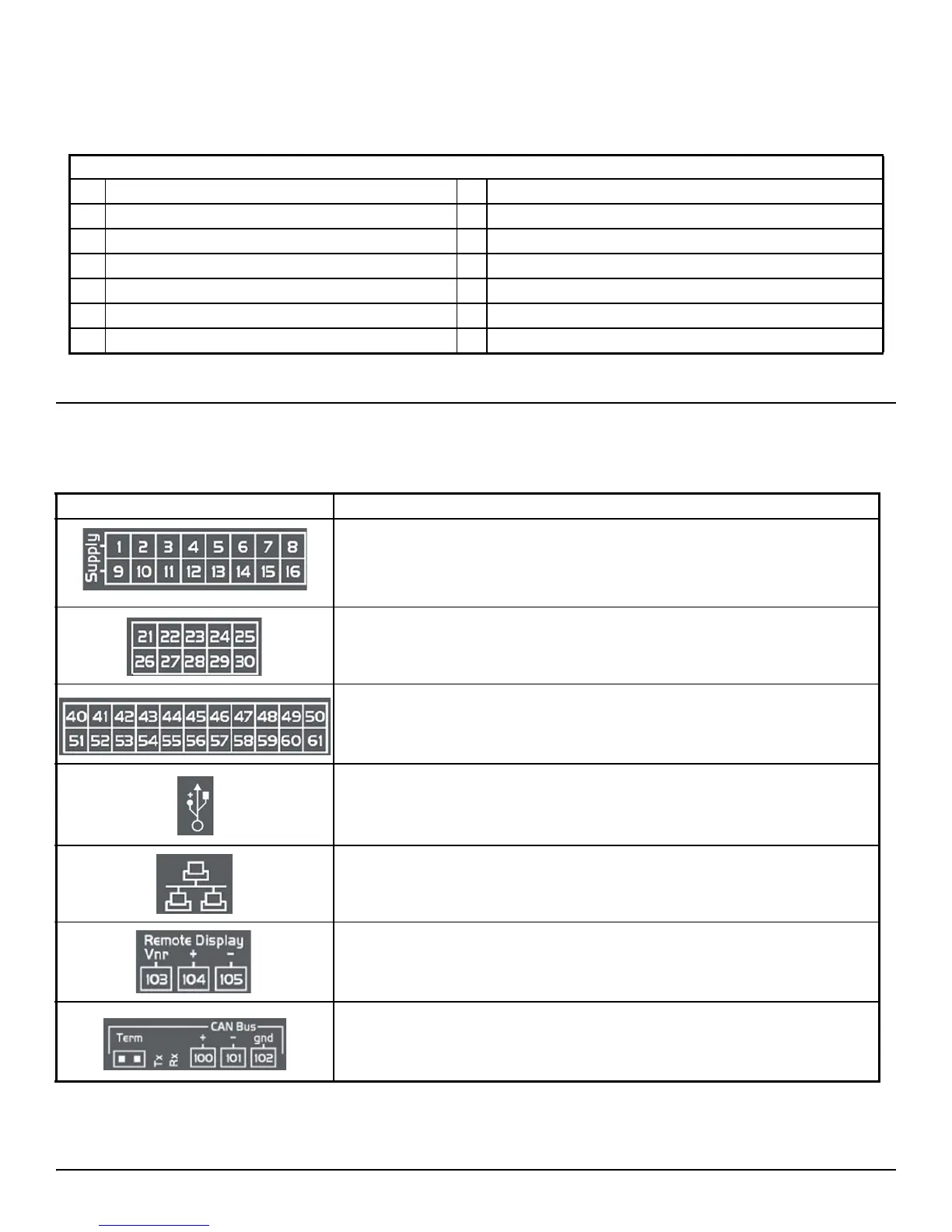
Connector Description
Connector for 24VAC/DC power supply.
Analog inputs (Pb1 - Pb6, PbC).
Additional power: +5VDC, +12VDC, Common (-)
Analog outputs (Out1 - Out4, Common).
Opto-insulated analog outputs (Out1 - Out6, GND)
24VAC/DC power supply required for the opto-insulated analog outputs
Voltage-free opto-insulated digital inputs (DI1 - DI20, IDC)
Opto-insulated 24VAC/DC digital inputs (DI1 - DI20, GND)
USB port for downloads (BIOS, ISaGRAF® application, maps of parameters, remote
display applications, network configuration, website) and uploads (log files).
TCP/IP Ethernet port. Also used for BACnet IP connection.
Connector for remote terminal (VISOGRAPH), maximum two (2) terminals per
iPro Case Controller.
CAN Bus port is used to connect the iPro Case Controller and XEV20D and IPX
modules.
Table 4-2 - iPro Connections and Descriptions