32 • iPro Case Controller I&O Manual FM V1.01 026-1738 Rev 1
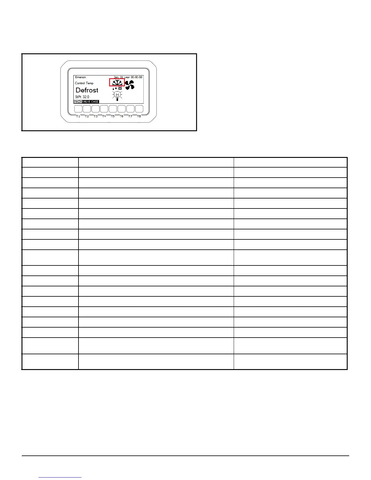
Figure 10-1 - Defrost Heater Relay Lockout Indicator
Parameter Description Range
DefTyp
Defrost type Electric/Hot gas
DefDur
Maximum defrost cycle duration 1-360 Minutes
MinDef
Minimum runtime of each defrost cycle 1-45 Minutes
Drip
Number of minutes of dripping time 0-30 Minutes
TermSet
Defrost termination temperature setpoint 0-99° Fahrenheit
MinI
Minimum time between the start of each defrost cycle 1-255 Minutes
DefDly
Minutes of delay of each defrost cycle start 0-30 Minutes
MaxWait
Maximum time the controller can stay in Wait mode 0-60 Minutes
dTS
Defrost term sensor selection Discharge Air, Defrost Term or Coil
Outlet
TempComb
Defrost termination sensor value combination method Minimum, maximum, average
TermTyp
Method of defrost termination Time, temperature or digital inputs
SHDef%
Defrost position of the electric expansion valves 0% or 100%
SuctionDef%
Defrost position of the EEPR 0% or 100%
SchHour
The scheduled starting hour of the defrost cycle 0-23 Hours
SchMin
The scheduled starting minute of the defrost cycle 0-59 Minutes
SchPerDay
The number of defrost cycles per day 0-6
defrAmpOn Amps required from the CT for defrost heater to be con-
sidered ON
0-60 Amps
defrAmpDel Time delay for defrost heater status to change to ON
once the threshold is reached.
1-90 Seconds
Table 10-8 - Defrost Parameter List