PACSystems™ RX3i and RSTi-EP CPU Reference Manual Section 6
GFK-2222AK October 2019
Serial I/O, SNP & RTU Protocols 166
X
16
+ X
15
+ X
2
+ 1 which in binary is 1 1000 0000 0000 0101. The CRC this polynomial
generates is known as CRC-16.
The discussion above can be implemented in hardware or software. One hardware
implementation involves constructing a multi-section shift register based on the
generating polynomial.
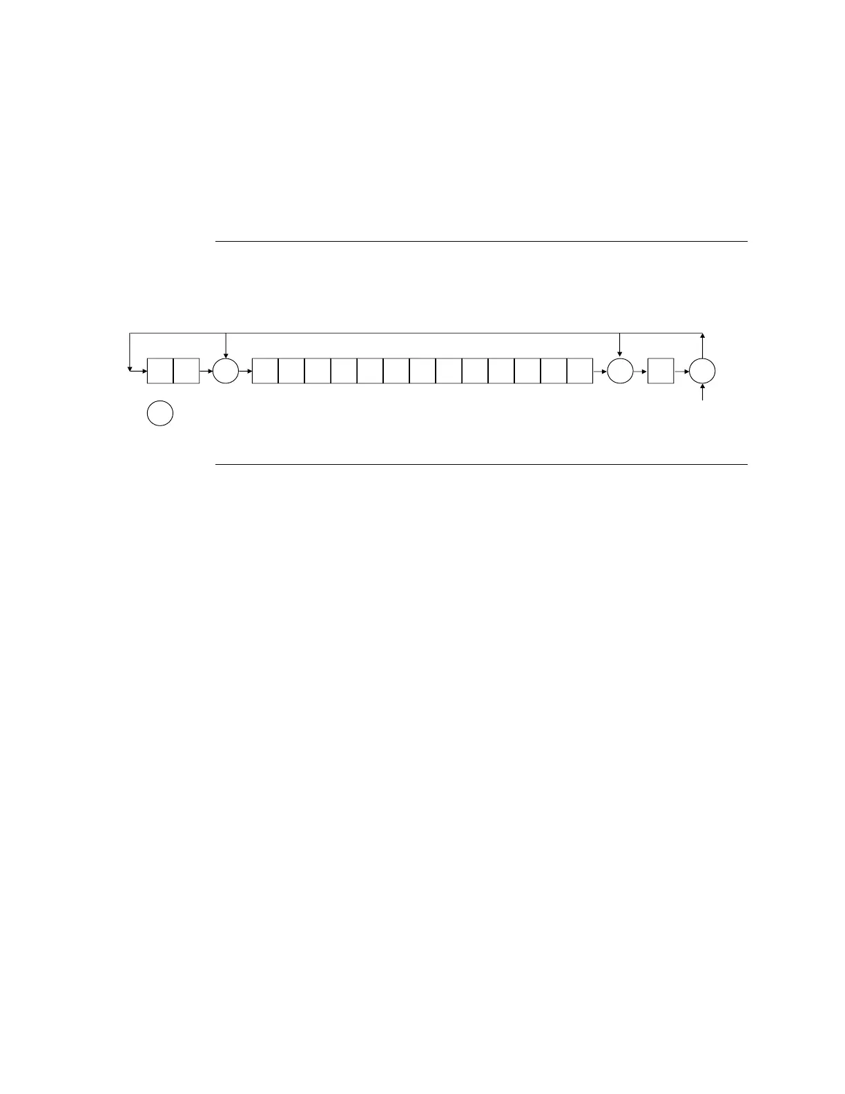
6.3.2.1 Cyclic Redundancy Check Register
Figure 22: CRC Register Operation
To generate the CRC, the message data bits are fed to the shift register one at a time. The
CRC register contains a preset value. As each data bit is presented to the shift register, the
bits are shifted to the right. The LSB is XORed with the data bit and the result is: XORed
with the old contents of bit 1 (the result placed in bit 0), XORed with the old contents of
bit 14 (and the result placed in bit 13), and finally, it is shifted into bit 15. This process is
repeated until all data bits in a message have been processed. Software implementation
of the CRC-16 is explained in the section below.

 Loading...