6
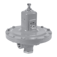
MR98 Series AD2000 Compliant
D-A-CH Region Only
▲
WARNING
Failure to follow these instructions or
to properly install and maintain this
equipment could result in an explosion,
re and/or chemical contamination
causing property damage and personal
injury or death.
Fisher™ backpressure regulators,
relief and relief valves must be
installed, operated and maintained
in accordance with federal, state and
local codes, rules and regulations and
Emerson instructions.
If a leak develops or if the outlet
continually vents gas, service to the
unit may be required. Failure to correct
trouble could result in a hazardous
condition. Only a qualied person shall
install or service the unit.
Installation, operation and maintenance
procedures performed by unqualied
person may result in improper adjustment
and unsafe operation. Either condition
may result in equipment damage or
personal injury. Call a qualied person
when installing, operating and maintaining
the MR98 Series Backpressure Regulators,
Relief and Relief Valves.
Introduction
Scope of the Manual
This manual provides instructions for the installation,
adjustment, maintenance and parts ordering
information of MR98 Series Backpressure Regulators
and Relief Valves. Instructions and parts lists for other
equipment mentioned in this Instruction Manual are
found in separate manuals.
Product Description
The MR98 Series Backpressure Regulator and Relief
Valves are suitable for multiple uid mediums including
liquid, gas, air and steam services. Typical applications
include use in but not limited to wash tanks, small
heaters, fuel and oil lines, air supply system, test
xtures and sterilizers.
Backpressure Regulator / Pressure Relief Valve—
Types MR98H and MR98HH Regulators are
direct-operated backpressure regulator/relief valve for
pressure control requiring constant outlet pressures
between 2 to 375 psig / 0.14 to 25.9 bar.
See Tables 1 through 4 for detailed breakdown of the
various construction oerings.
Principle of Operation
Relief or backpressure valves respond to changes in
upstream pressure. Pressure changes register under
the diaphragm (see Figure 2) through a registration hole
in the valve body or through an external control line.
When the pressure increases above the spring setting,
the pressure underneath the diaphragm overcomes the
spring compression. This causes the valve plug to move
away from the orice. The ow path through the valve
is open and excess pressure is vented. When upstream
pressure drops below setpoint, the valve closes.
Installation
▲
WARNING
Personal injury or system damage may
result if this backpressure regulator or
relief valve is installed where service
conditions could exceed the limits given
on the Specications section and/or
regulator nameplate.
Additionally, physical damage to the
backpressure regulator or relief valve
may result in personal injury or property
damage due to escaping of accumulated
gas. To avoid such injury and damage,
install the backpressure regulator or
relief valve in a safe location.
Under enclosed conditions or indoors,
escaping gas may accumulate and be an
explosion hazard. In this case, the vent
should be piped outdoors.
For regulator constructions with a
spring case vent, the vent should be
kept open to permit free ow of gas
to the atmosphere. Protect openings
against entrance of rain, snow, insects
or any other foreign material that may
plug the spring case vent or vent line.
 Loading...