Do you have a question about the Emerson NZ Series and is the answer not in the manual?
Discusses methods and devices to prevent overpressure in the system to ensure safety.
Explains the operation and function of the integral slam-shut safety device.
Covers general guidelines and precautions applicable to all regulator installations.
Provides detailed instructions for adjusting the pilot control screw for desired pressure settings.
Step-by-step guide for bringing the regulator into operation after installation.
Details specific procedures for maintaining the main valve assembly components.
Procedures for servicing the actuator and diaphragm components of the regulator.
General maintenance procedures applicable to all JP Series pilot assemblies.
Maintenance procedures for the second stage of JPLO and JPHO Series pilot assemblies.
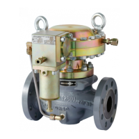
The NZ/NZ-M and NZOS/NZOS-M Series are pilot-operated pressure reducing regulators designed for a wide range of high-pressure applications. These include high-pressure transmission, power plant skids, city gate stations, large capacity gas distribution systems, CNG stations, industrial skids, and commercial installations. The primary function of these regulators is to provide accurate and reliable pressure control across the entire flow range. They are suitable for use with natural gas, LP-Gas, and other non-corrosive gases.
The regulator operates by utilizing inlet pressure as the operating medium, which is then reduced through pilot operation to load the actuator diaphragm. The loading pressure, in turn, regulates the outlet pressure by moving a sleeve towards or away from the seat. Any change in the outlet pressure affects the balance between the outlet pressure chamber and the control spring in the second stage of the pilot. If the outlet pressure decreases, the spring pushes the diaphragm downwards, moving the pilot disk away from the orifice and increasing the loading pressure. This increased loading pressure pushes the main diaphragm up, increasing the distance between the seat and the sleeve, allowing more flow through the main valve's orifice. Conversely, if the outlet pressure increases, the pilot reduces the loading pressure, moving the sleeve closer to the seat, which decreases the flow rate and maintains the desired outlet pressure.
The NZOS/NZOS-M Series includes an integral slam-shut device, offering either overpressure protection (OPSO) or a combination of overpressure and underpressure protection (OPSO/UPSO). This device completely shuts off the gas flow to the downstream system when pressure fluctuations sensed through a control line reach a predefined set pressure. Once activated, the slam-shut device must be manually reset before the regulator can be returned to service.
The NZ/NZ-M and NZOS/NZOS-M Series regulators are designed to bleed no gas to the atmosphere during normal operation, making them suitable for installation in enclosed locations or pits without requiring elaborate venting systems. In pits subject to flooding, the pilot spring case can be vented above the expected flood level to ensure the pilot diaphragm is always exposed to atmospheric pressure.
The JP Series pilots, which are integral to these regulators, come in various configurations. Single diaphragm pilots (JPLO, JPHO, JPLOW, JPHOW, JPLOM, JPHOM) are used for single-stage pressure reducing, as monitor or working pilots in wide-open monitor systems, or as working pilots in working monitor systems. In case of failure, these single diaphragm pilots will cause a fail-open reaction of the regulator. Double diaphragm pilots (JPLC, JPHC, JPLCW, JPHCW, JPLCM, JPHCM) are also available for similar applications, but in case of failure, they will cause a fail-close reaction of the regulator. Most JP Series pilots include an integral 10-micro filter, except for the JPLOW/JPHOW/JPLCW and JPHCW types. Remote pressure loaded pilots (JPXX-P) are also available, offering the same outlet pressure range and function as spring-loaded types, with a maximum loaded pressure of 10 Bar.
Monitoring systems are a key feature, providing overpressure protection by containment without continuously venting gas to the atmosphere. In a wide-open monitoring system, the working regulator controls the system's outlet pressure, while the monitor regulator is set to a higher outlet pressure. If the working regulator fails, the monitor regulator takes control and maintains the outlet pressure at its setpoint. In a working monitoring system, the upstream regulator acts as the monitoring regulator, controlling an intermediate pressure during normal operation, ensuring both units are always operating and easily checked. If the working regulator fails, the monitoring pilot senses the increase in outlet pressure and takes control.
Installation requires careful attention to the flow direction, ensuring the regulator is installed with the flow arrow matching the process fluid direction. For optimal performance, the regulator is typically installed in a horizontal pipeline with the actuator above the body. Proper gaskets should be used with flanged connections. A critical safety consideration is the installation of a vent line from the regulator pilot to a remote, safe location, away from air intakes or hazardous areas, to prevent accumulation of vented gas in case of malfunction. The vent opening must be pointed down and protected from condensation or clogging. Sense lines for the pilot and main valve should be connected to a straight run of pipe at least five pipe diameters from the regulator outlet to avoid abnormal flow velocities.
Startup and adjustment procedures involve ensuring block valves isolate the regulator, vent valves are closed, and any bypass is in operation. The pilot adjusting screw is used to set the desired outlet pressure, with careful monitoring using a pressure gauge. For monitor regulators, the set point is typically higher than the working regulator's set pressure. The restrictor on the pilot controls the regulator's proportional band droop and speed of response, and it should be adjusted carefully to prevent hunting of the stable outlet pressure.
Maintenance is crucial for the longevity and safe operation of the regulator. Parts are subject to normal wear and require periodic inspection and replacement. Before any maintenance, the regulator must be isolated from the pressure system, and all pressure must be released from the pilot and main valve. After reassembly, an external leakage test and lock-up test must be performed. Regular checks include inspecting for leaks and observing outlet pressure stability. Periodic maintenance involves lockup pressure tests for Type NZ and shutoff pressure tests for Type NZOS, as well as cleaning and inspecting the seat, diaphragm, O-rings, and other soft parts. Any worn or damaged parts must be replaced.
Specific maintenance procedures are detailed for the main valve, actuator, diaphragm, travel indicator, balance stem assembly, and JP Series pilots. These procedures involve disassembling components, inspecting for wear or damage, replacing parts as needed, and reassembling with proper lubrication and torque values. For the JP Series pilots, filter maintenance, first stage maintenance, second stage maintenance, and restrictor maintenance are outlined, emphasizing careful handling of components and ensuring proper reassembly.
| Inputs | Digital Inputs, Analog Inputs |
|---|---|
| Outputs | Digital Outputs, Analog Outputs |
| Output Voltage | 24 VDC (Digital Outputs), 0-10 VDC (Analog Outputs) |
| Output Current | 0-20 mA (Analog Outputs) |
| Protection | Short Circuit Protection, Overload Protection, Reverse Polarity Protection |
| Controller Type | Programmable Logic Controller (PLC) |
| Communication Protocol | Ethernet/IP, Modbus TCP/IP, Modbus RTU/ASCII, Profibus DP (optional) |
| Power Supply | 24 VDC |
| Input Voltage Range | 0-10 VDC, 0-20 mA (Analog Inputs), 24 VDC (Digital Inputs) |
| Operating Temperature | -20°C to +60°C |
| Storage Temperature | -40°C to +70°C |
| Dimensions | Varies depending on the specific model, typically around 100mm x 150mm x 75mm |
| Weight | Varies depending on the specific model, typically around 0.5 kg |