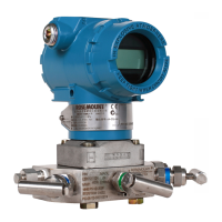
Do you have a question about the Emerson Rosemount 8732EM and is the answer not in the manual?
Details the procedures and requirements for returning equipment to Emerson.
Determining necessary options and configurations based on application requirements.
Explanation of user-selectable hardware switches for power and security settings.
National, local, and plant electrical installation requirements for the transmitter.
Specifications for transmitter conduit entry ports and connection standards.
Guidelines for using conduits, including intrinsic safety and cable bundling.
Wiring instructions specific to Rosemount transmitters mounted directly on the sensor.
Wiring instructions for Rosemount transmitters mounted remotely from the sensor.
Specifications for shielded twisted pairs, cable lengths, and combination cables.
Procedure for preparing cable ends for terminal connections, including stripping and shielding.
Views and wiring table for remote junction box terminal blocks for sensor and transmitter.
Detailed wiring diagrams for component and combination cables using the 8732EM transmitter.
Terminal block layouts and assignments for AC and DC versions of the transmitter.
Information on AC and DC power supply requirements and current needs for the transmitter.
Recommendations for Modbus RTU signal wiring using RS-485 interface.
Instructions for navigating and using the Local Operator Interface (LOI) for configuration.
Details on configuring Modbus communication parameters like address and byte order.
Setting the communication speed for the transmitter's Modbus network.
Configuring the error-checking methodology for data transmission.
Setting the number of stop bits for the Modbus data packet.
Specifying the units for flow rate display, including volume and mass units.
Setting the transmitter to match the actual sensor line size for accurate measurements.
Information on the sensor calibration number and its location on the sensor tag.
| Brand | Emerson |
|---|---|
| Model | Rosemount 8732EM |
| Category | Transmitter |
| Language | English |
