Do you have a question about the Emerson Rosemount 5402 and is the answer not in the manual?
Explains the working principle of the Rosemount 5400 Level Transmitter using radar technology.
Illustrates various applications for the Rosemount 5400 in different industries and conditions.
Details the HART, FOUNDATION Fieldbus, and RS-485 Modbus communication system architectures.
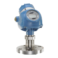
Identifies and describes the physical components of the Rosemount 5400 Level Transmitter.
Provides guidance on selecting the appropriate antenna based on application and dielectric constant.
Crucial safety precautions to ensure personnel safety during mechanical installation procedures.
Step-by-step instructions for the proper mechanical installation of the transmitter.
Key factors to consider before mounting the transmitter for optimal performance and safety.
Recommendations for selecting an optimal mounting position to avoid interference and ensure accuracy.
Specific recommendations and procedures for installing the transmitter using still-pipes.
Special considerations for different nozzle types and antenna combinations during installation.
Detailed steps for installing the cone antenna using a flange connection.
Essential safety instructions to be followed during electrical installation.
Specifies the necessary wiring and power supply requirements for proper operation.
Step-by-step guide on how to connect the transmitter wiring and power supply.
Details the power supply voltage and load resistance requirements for HART communication.
Specifies the power supply voltage requirements for FOUNDATION Fieldbus communication.
Instructions for connecting the HART to Modbus Converter (HMC) to the transmitter.
Procedures for establishing HART communication, including terminal connections.
Steps to connect the transmitter to MA/MB terminals for HART communication.
Critical safety precautions to ensure safe configuration procedures.
General introduction to the transmitter configuration process.
Details essential parameters for standard transmitter configuration.
Setting up tank shape, dimensions, and reference points for accurate measurement.
Procedures for configuring volume calculations based on tank shape or strapping tables.
Configuring the analog output range, primary variable, and alarm modes.
Steps for calibrating the level and distance measurements for accuracy.
Methods for fine-tuning the transmitter to handle disturbing echoes and noise.
Instructions for configuring the transmitter using the Rosemount Radar Master software.
Step-by-step guide for installing the RRM software for HART communication.
Procedures for configuring the transmitter using a Field Communicator device.
General information and function block diagram for FOUNDATION Fieldbus.
An application example demonstrating configuration for level measurement.
Instructions for configuring the Tri-Loop converter for additional analog outputs.
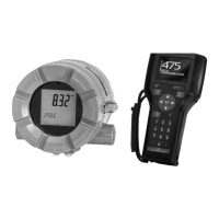
How to view measurement data and device information on the transmitter's display panel.
Customizing which variables are shown on the transmitter's LCD display.
How to view measurement data remotely using AMS Suite or DeltaV software.
A list and explanation of error messages displayed on the LCD.
Interpreting error codes indicated by the transmitter's LED.
Critical safety precautions for performing service and troubleshooting.
A guide to common malfunctions, their causes, and recommended actions.
Using the Echo Curve to analyze measurement signals and diagnose issues.
Steps to resolve issues when the surface pulse is not detected.
Procedure for identifying and registering false echoes to improve measurement accuracy.
Guide to using the Echo Curve Analyzer tool in RRM for signal analysis.
Procedure for calibrating the analog output current of the transmitter.
Instructions for creating a backup of the transmitter's configuration settings.
How to retrieve and interpret diagnostic information from the device.
Procedure for resetting the transmitter to its original factory default settings.
How to enable password protection to prevent unintentional configuration changes.
Information on various diagnostic messages, including device status, errors, and warnings.
Common application errors and their potential causes and solutions.
Guide to resolving common transmitter malfunctions not covered by diagnostic messages.
Crucial safety precautions specific to Safety Instrumented Systems.
Introduction to the Rosemount 5400's role in SIS applications with QS Prior-Use.
Details the functional specifications for the transmitter in SIS applications.
Guidelines for installing the transmitter in Safety Instrumented Systems.
Configuration steps and parameters specific to SIS requirements.
Setting alarm and saturation levels critical for safety function.
General functional capabilities and application suitability of the transmitter.
Details on the 4-20 mA HART output signal, including saturation levels and load limitations.
Technical performance metrics including accuracy, measuring range, and interference effects.
Information on how dielectric constant affects the measuring range.
Specific features and capabilities for applications involving solids measurement.
Details on physical dimensions, materials, weight, and ingress protection.
Guidance for selecting appropriate materials for wetted parts based on process conditions.
Specifications for various tank connection types and antenna options.
Guide to ordering the transmitter, including model codes, options, and certifications.
Details regarding compliance with European Union directives.
Standard certification for transmitters used in ordinary locations.
Information on FCC and Industry Canada compliance standards.
Guidelines for installing equipment in North American electrical codes.
Details on Explosion-proof, Dust-ignition-proof, and Intrinsic Safety certifications for USA.
Details on Explosion-proof and Intrinsically Safe certifications for Canada.
Details on ATEX Flameproof and Intrinsic Safety certifications for Europe.
Reference to installation drawings for maintaining certified ratings in hazardous locations.
Critical safety precautions for performing advanced configuration.
Fine-tuning tank geometry parameters like distance and minimum level offsets.
Adjusting hold off distance to manage echoes near the antenna.
Fine-tuning transmitter parameters for specific application needs.
Functions to manage echoes near the tank bottom and detect empty tank states.
Managing echoes caused by reflections from the tank roof to the surface.
Eliminating ghost echoes below the product surface using echo tracking.
Adjusting hold off distance to avoid misinterpreting nozzle echoes as surface echoes.
Metrics indicating surface signal integrity relative to noise for maintenance.
Steps to check if the device supports Signal Quality Metrics.
How to display and interpret Signal Quality Metrics values within the RRM software.
General guide on performing proof tests to detect transmitter failures.
Step-by-step instructions for performing proof tests with a Field Communicator.
Step-by-step instructions for performing proof tests using RRM software.
Step-by-step instructions for performing proof tests using AMS Suite.
General information about the Level Transducer Block, its parameters, errors, and diagnostics.
Detailed descriptions of all parameters within the Level Transducer Block.
Information on device errors detected within the Transducer Block.
List of parameters available for accessing database and input registers.
Parameters for advanced configuration, including echo filtering and simulation.
General information about the Resource Block and its functions.
Detailed descriptions of all configurable parameters within the Resource Block.
How the Resource Block coordinates Plantweb alerts and alarm priorities.
Defines the five priority levels used for alarms within the Resource Block.
Provides recommended actions based on the type and event of active Plantweb alerts.
General information on the Analog-Input function block and its capabilities.
Lists and explains error conditions supported by the Analog-Input block.
How alarms are generated and prioritized based on the OUT value and alarm limits.
Required parameters and steps to configure the Analog-Input block.
| Device Type | Non-Contacting Radar Level Transmitter |
|---|---|
| Measurement Type | Level |
| Frequency | 26 GHz |
| Output Signal | 4-20 mA HART |
| Communication Protocol | HART |
| Enclosure Rating | IP68 |
| Process Temperature | -40 to 85 °C |
| Power Supply | 24 VDC |

