78
Reference Manual
00809-0100-4026, Rev KC
Operation and Maintenance
October 2018
Operation and Maintenance
4.9 HART
®
communication
4.9.1 Power requirements
The Rosemount 5400 Series transmitter operates with a power supply ranging from
16 - 42.4 Vdc (16 - 30 Vdc in IS applications, 20 - 42.4 Vdc in explosion-proof/flameproof applications
and in non-sparking/energy-limited applications).
All configuration tools for HART communication, such as the Field Communicator and Rosemount Radar
Master, require a minimum load resistance (R
L
) of 250 within the loop in order to function properly.
Terminals in the transmitter housing provide connections for signal wiring. The Rosemount 5400
operates with the following power supplies:
Table 4-1. Minimum Input Voltage (U
I
) at Different Currents
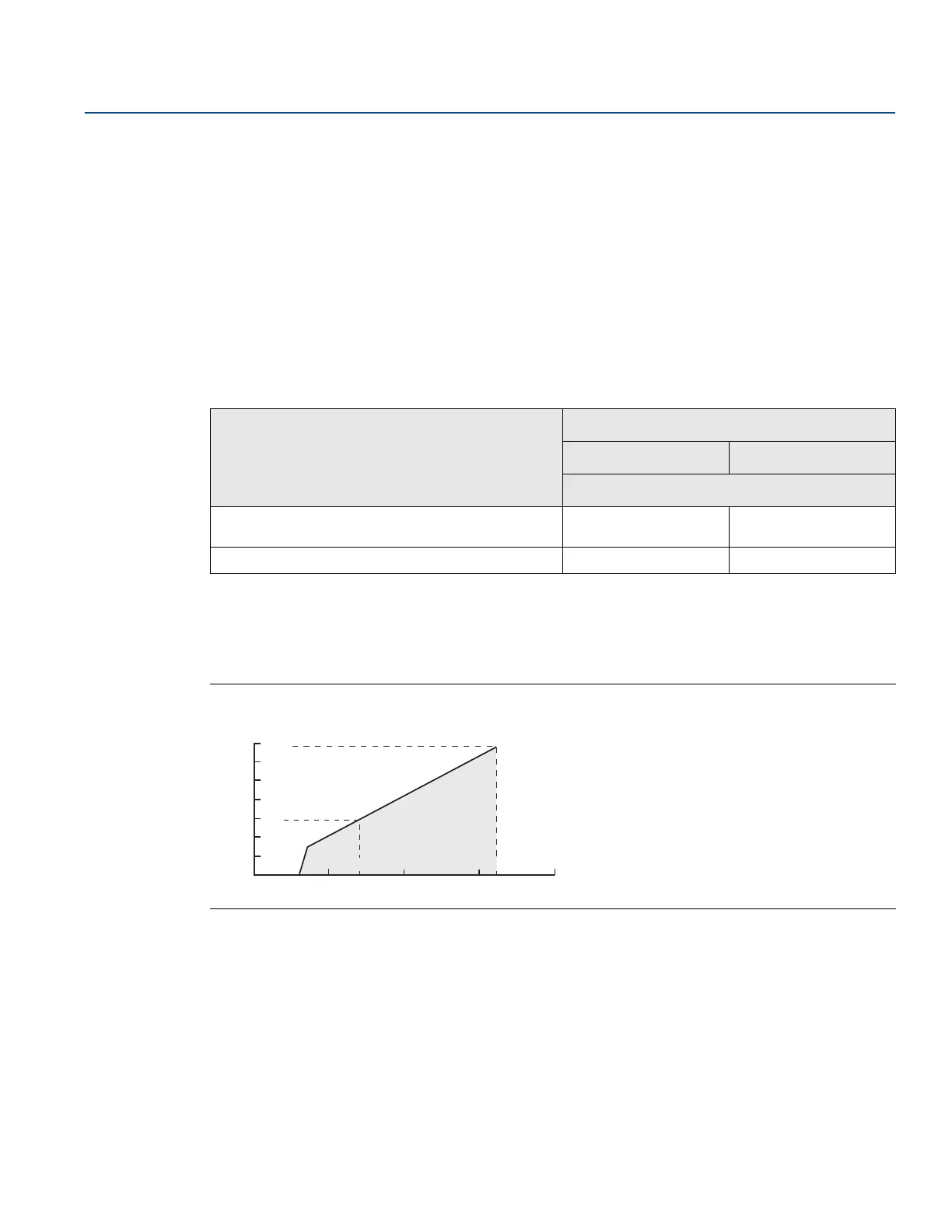
4.9.2 Load limitations
Maximum load resistance (R) is determined by the voltage level of the external power supply (U
E
), as
described by:
Figure 4-2. Non-Hazardous Installations, and Non-Sparking/Energy-Limited Power Supply
Hazardous approval
Current
3.75 mA 21.75 mA
Minimum input voltage (U
I
)
Non-Hazardous Installations and Intrinsically Safe
Installations
16 Vdc 11 Vdc
Explosion-proof/Flameproof Installations 20 Vdc 15.5 Vdc
10 20
16
30
200
400
600
800
1000
1200
1400
40 50
42.424
586
1387
External Power Supply Voltage U
E
(V)
Maximum Load Resistance R()
Operating
region