Advanced Configuration
October 2018
Reference Manual
00809-0100-4026, Rev KC
Advanced Configuration
259
C.2.3 Hold Off distance
This parameter should only be changed if there are disturbing objects close to the antenna. No valid
measurements are possible above the Hold Off Distance. By increasing the Hold Off Distance, the
measuring range is reduced. See “Hold Off setting” on page 270 for more information.
C.2.4 Calibration distance
The Calibration Distance is defaulted to zero. It is used to adjust the transmitter so measured levels
match hand-dipped or otherwise known product levels. Normally, a minor adjustment is necessary.
There may, for example, be a deviation between the actual tank height and the value from tank
drawings, which are usually stored in the transmitter database.
Non-metallic (for example, plastic) vessels and installation geometry may introduce an offset for the zero
reference point. This offset may be up to ± 10 mm. The offset can be compensated for using Calibration
Distance.
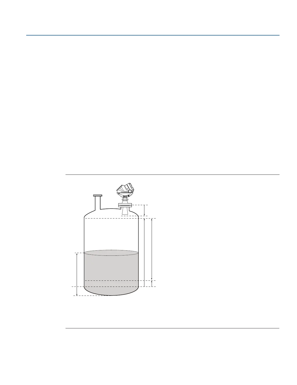
C.3 Advanced analog output settings
The 20 mA Upper Range Value should be outside the Hold Off Distance (see “Hold Off distance” on
page 259) in order to utilize the full range of the analog output.
Figure C-2. Advanced Range Value Settings
A. Product level E. 20 mA Upper Range Value (URV)
B. Min level offset (C) F. Range 0-100%
C. Upper reference point G. 4 mA Lower Range Value (LRV)
D. Hold off distance H. Lower reference point (Level = 0)