32
Reference Manual
00809-0100-4026, Rev KC
Mechanical Installation
October 2018
Mechanical Installation
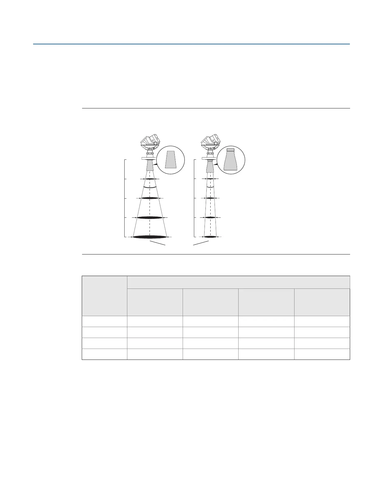
3.3.8 Beam width
The following recommendations should be considered when mounting the transmitter:
The transmitter should be mounted with as few internal structures as possible within the beam angle.
The flat tank wall can be located within the antenna beam angle if there is a minimum distance from
the transmitter to the tank wall (see Figure 3-20 for preferred installation).
Figure 3-21. Beam Width at Various Distances from the Flange
Table 3-6. Beam Width for the Rosemount 5402 Model (in ft [m])
Distance
Antenna
2 in. (DN 50) cone/
process seal
3 in. (DN 80) cone/
process seal
4 in. (DN 100)
cone/
process seal
Parabolic
16 ft (5 m)
4.9 (1.5) 3.3 (1.0) 3.3 (1.0) 1.3 (0.4)
33 ft (10 m)
9.8 (3.0) 6.6 (2.0) 4.9 (1.5) 2.6 (0.8)
49 ft (15 m)
14.8 (4.5) 9.8 (3.0) 8.2 (2.5) 3.9 (1.2)
66 ft (20 m)
19.7 (6.0) 13.1 (4.0) 9.8 (3.0) 5.2 (1.6)
Distance
Rosemount 5401
(low frequency)
Rosemount 5402
(high frequency)
16 ft (5 m)
33 ft (10 m)
49 ft (15 m)
66 ft (20 m)
Beamwidth
 Loading...


