81
Reference Manual
00809-0100-4026, Rev KC
Electrical Installation
October 2018
Electrical Installation
4.9.4 Intrinsically safe power supply
With an intrinsically safe power supply, wire the transmitter as shown in Figure 4-6.
Note
Make sure the instruments in the loop are installed according to intrinsically safe field wiring practices.
Installation also needs to comply with the applicable installation/control drawing. See “Approval
drawings” on page 251.
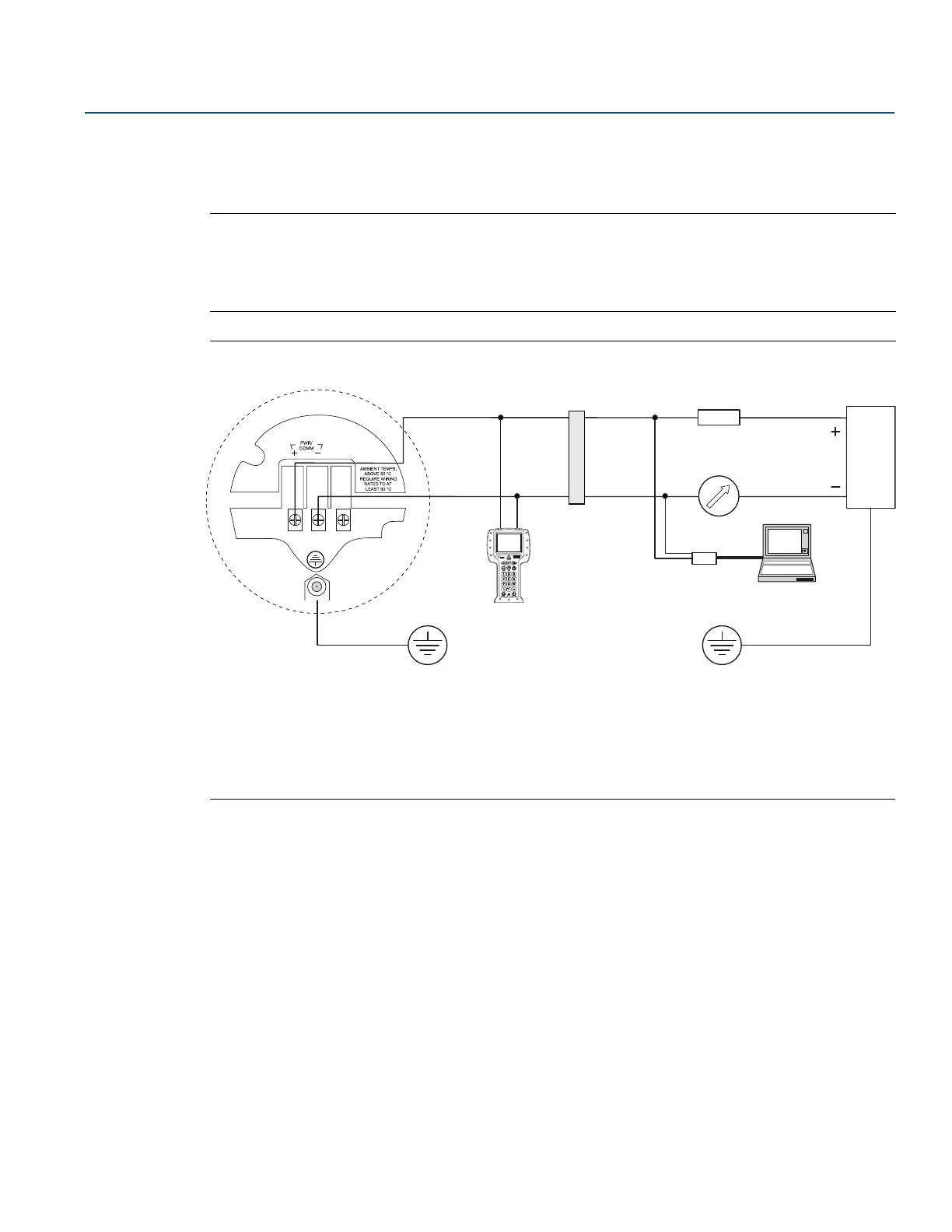
Figure 4-6. Wiring Diagram for Intrinsically Safe Power Supply (HART)
The Field Communicator and the HART modem require a minimum load resistance within the loop of
250 to function properly. For maximum load resistance see Figure 4-3.
For Safety Instrumented Systems information, see “Safety Instrumented Systems (4-20 mA Only)” on
page 197.
A. Rosemount 5400 E. HART modem
B. Field Communicator F. PC
C. Approved IS barrier G. Power supply
D. R
L
=250
For IS parameters, see Appendix B: Product Certifications.
A
B
C
D
E
F
G