79
Reference Manual
00809-0100-4026, Rev KC
Electrical Installation
October 2018
Electrical Installation
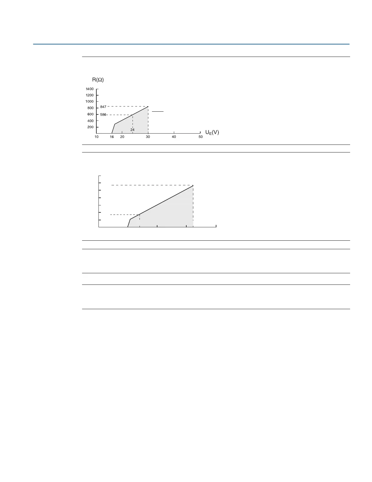
Figure 4-3. Intrinsically Safe Installations
Figure 4-4. Explosion-Proof/Flameproof Installations
Note
For flameproof/explosion-proof installations, the diagram is only valid if the HART load resistance is at
the + side and if the - side is grounded. Otherwise, the load resistance value is limited to 435 .
Note
Rosemount 5400 with flameproof/explosion-proof output have a built-in barrier; no external barrier
needed.
External Power Supply Voltage U
E
(V)
Maximum Load Resistance R()
Operating
region
10 20 30
200
400
600
800
1000
1200
1400
40 50
24 42.4
1148
348
External Power Supply Voltage U
E
(V)
Maximum Load Resistance R()
Operating
region








 To Next Page