2-3-3 Z11MA
1-A. Preliminary/Final Checking and
Alignment of Tape Path
Purpose:
To make sure that the tape path is well stabilized.
Symptom of Misalignment:
If the tape path is unstable, the tape will be damaged.
Note: Do not use an Alignment Tape for this proce-
dure. If the unit is not correctly aligned, the tape may
be damaged.
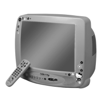
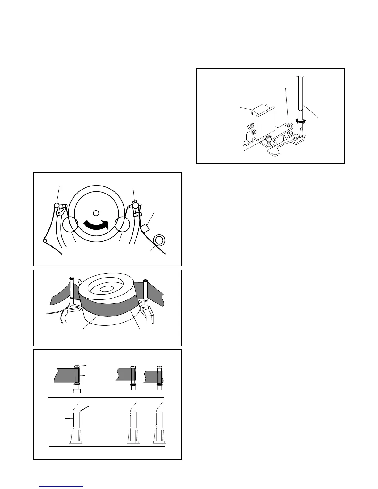
1. Play back a blank cassette tape and check to see
that the tape runs without creasing at Guide Rollers
[2] and [3], and at points A and B on the lead sur-
face. (Refer to Fig M3 and M4.)
2. If creasing is apparent, align the height of the guide
rollers by turning the top of Guide Rollers [2] and
[3] with a Guide Roller Adj. Screwdriver. (Refer to
Fig. M3 and M5.)
3. Check to see that the tape runs without creasing at
Take-up Guide Post [4] or without snaking between
Guide Roller [3] and AC Head. (Fig. M3 and M5)
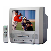
4. If creasing or snaking is apparent, adjust the Tilt
Adj. Screw of the AC Head. (Fig. M6)
1-B. X Value Alignment
Purpose:
To align the Horizontal Position of the Audio/Control/
Erase Head.
Symptom of Misalignment:
If the Horizontal Position of the Audio/Control/Erase
Head is not properly aligned, maximum envelope can-
not be obtained at the Neutral position of the Tracking
Control Circuit.
1. Connect the oscilloscope to J189 (PB-C-MONI)
and J116 (CTL) on the Main CBA. Use J190 (RF-
SW) as a trigger.
2. Play back the Gray Scale of the Alignment Tape
(FL8N) and confirm that the PB FM signal is
present.
3. Set the Tracking Control Circuit to the center posi-
tion by pressing CH UP button then “ PLAY ” button
on the unit. (Refer to note on bottom of page
2-3-4.)
4. Use the X-Value Adj. Screwdriver so that the PB
FM signal at J189 (PB-C-MONI) is maximum. (Fig.
M6)
5. Press CH UP button on the unit until the CTL wave-
form has shifted by approx. +2msec. Make sure
that the envelope is simply attenuated (shrinks in
height) during this process so that you will know
the envelope has been at its peak.
Guide Roller [2]
Guide Roller [3]
A
B
Take-up Guide Post [4]
AC Head
Fig. M3
Lead Surface of Cylinder
Tape
Fig. M4
Guide Roller
Tape
Correct
Incorrect
Take-up Guide
Post
Tape
Fig. M5
Azimuth Adj. Screw
X-Value Adj.
Screwdriver
Tilt Adj. Screw
AC Head
Fig. M6
 Loading...