Do you have a question about the Emerson SKB3400055 and is the answer not in the manual?
Explains warning, caution, and note indicators.
General safety advice regarding high voltages.
Requirements for safe system integration and personnel.
Information regarding fire enclosure requirements for the drive.
Recommendations for motor installation and parameter settings.
Information on using brake control functions safely.
Caution regarding profound effects of parameter changes.
Detailed safety precautions for electrical installation.
Drive intended for mounting in a protective enclosure.
Drive enclosure is not a fire enclosure; separate enclosure required.
Diagram and table for required spacing between drives.
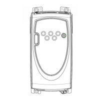
Diagram identifying key features and connections of the drive.
Diagrams for power terminal connections for different drive sizes.
Requirement for supply protection against overload and short circuits.
Safety warnings about braking resistor heat and protection.
Information on ground leakage current and permanent ground connections.
Types of ELCB/RCD and their compatibility with drives.
Electromagnetic compatibility information.
Recommendations and function of the internal EMC filter.
Instructions and diagrams for removing the EMC filter.
Additional EMC measures for stringent requirements.
Safety warnings and specifications for control terminals.
Description of the MODE, UP, and DOWN keys for programming.
Function of the START and STOP/RESET keys.
Procedure for navigating and editing parameters via keypad.
Levels of parameter access and security settings.
Setting up and unlocking security codes for parameter access.
Procedure for resetting drive parameters to factory defaults.
Details for Level 1 parameters (01-10).
Details for Level 2 parameters (11-70).
Details for Level 3 parameters (71-95).
Read-only parameters used for fault diagnosis.
Setup of drive configuration based on parameter 05.
Terminal diagram and parameters for PID control configuration.
Setting motor rated current for overload protection.
Selects autotune mode for motor setup.
Minimum required control terminal connections for commissioning.
Minimum required control terminal connections for keypad control.
Entering motor rated current, speed, voltage, and power factor.
Steps to prepare for and perform motor autotune.
List of trip codes, conditions, and possible causes.
UL listing requirements for installation and components.
How motor overload protection operates and is set.
| Efficiency | 98% |
|---|---|
| Protection Level | IP20 |
| Input Voltage | 380-480V |
| Output Power | 55kW |
| Cooling Method | Air-cooled |


