WARNING
To avoid personal injury resulting from sudden
release of pressure, isolate the regulator from all
pressure before attempting disassembly.
Parts List
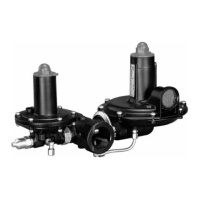
Type FL Main Valve (Figure 1)
Key Description
1 Inlet Flange
2* Anti-Friction Ring, (6 required)
3* O-ring (3 required)
4* Body O-ring
DN 25, 50, 80 and 100 / NPS 1, 2, 3 and 4 (2 required)
DN 150 and 200 / NPS 6 and 8
5 Socket Head Screw
DN 25, 50, 80, 100 and 150 / NPS 1, 2, 3, 4 and 6
(16 required)
DN 200 and 250 / NPS 8 and 10 (24 required)
6 Spring
7 Tube Fitting
8 Inlet Plate
9 Flange Bolt
DN 25, 50, 80 and 100 / NPS 1, 2, 3 and 4 (16 required)
DN 150 / NPS 6 (24 required)
DN 200 / NPS 8 (30 required)
DN 250 / NPS 10 (36 required)
10* Diaphragm
11 Inlet Body Cover, not available for DN 250 / NPS 10
12 Outlet Plate
13 Outlet Body Cover
14 Washer
DN 25, 50, 80 and 100 / NPS 1, 2, 3 and 4 (16 required)
DN 150 / NPS 6 (24 required)
DN 200 / NPS 8 (30 required)
DN 250 / NPS 10 (36 required)
15 Nut
DN 25, 50, 80 and 100 / NPS 1, 2, 3 and 4 (16 required)
DN 150 / NPS 6 (24 required)
DN 200 / NPS 8 (30 required)
DN 250 / NPS 10 (36 required)
16 Sleeve
17 Tube Fitting
18* O-ring
19 Disk Holder
Type FL
Type FL-SR, FL-SRII, FL-SR/SRS or FL-SRII/SRS
(1)
20* Disk
21 Disk Retainer
22 Outlet Flange
23 Gasket
24 Spacer
(2)
25 Socket Head Screw
26* O-ring
27 Socket Head Screw
DN 25 and 50 / NPS 1 and 2 (6 required)
DN 80 and 100 / NPS 3 and 4 (12 required)
DN 150 / NPS 6 (8 required)
DN 200 / NPS 8 (16 required)
DN 250 / NPS 10 (20 required)
28* O-ring
29 Nameplate
30 Nameplate Sticker
31 Drive Screw (4 required)
32 Flow Arrow
33 Spring Collet, not available for DN 250 / NPS 10
34 Indicator Stem, not available for DN 250 / NPS 10
35* O-ring
36 Indicator Fitting
37A* O-ring
37B* O-ring
38 Indicator Bushing
39 Indicator Scale
40 Indicator Cover, not available for DN 250 / NPS 10
43 Type SR Silencer
46* O-ring
47* O-ring
48 Washer, not available for DN 250 / NPS 10
59 Eyebolt
DN 150 / NPS 6 (2 required)
DN 200 / NPS 8 (2 required)
DN 250 / NPS 10 (2 required)
61 Pin (DN 150 / NPS 6 only) (8 required)
62 Screw
DN 200 and 250 / NPS 8 and 10 only (6 required)
63 Washer
DN 200 and 250 / NPS 8 and 10 only (6 required)
64 Socket Head Screw
DN 150 / NPS 6 (16 required)
DN 200 / NPS 8 (20 required)
65 Spring Pin
DN 200 and 250 / NPS 8 and 10 only
66* Back-up Rings (2 required)
67 Disk Support (2 required)
Type SRS Main Valve (Figure 3)
Key Description
200 Body
201 Retainer
202 Stud, not available for DN 200 / NPS 8 body
202 Nut, for DN 200 / NPS 8 body only
203 Attenuator Plate, not available for DN 200 / NPS 8 body
204 Spring Pin
DN 25, 50 and 80 / NPS 1, 2 and 3 (2 required)
DN 100 and 150 / NPS 4 and 6
205 Ring
206 Nut (3 required), not available for DN 200 / NPS 8 body
206 Spacer, for DN 200 / NPS 8 body only
207 Attenuator Plate
208 Attenuator Plate
*Recommended Spare Part
1. DN 200 and 250 / NPS 8 and 10 are available only with Types SRII and SRII/SRS silencers.
2. For DN 200 / NPS 8 Type FL with Type SRS, the spacer will be installed upstream and not downstream. Please see DN 200 / NPS 8 for Part Number.
Key Description

 Loading...