Do you have a question about the Emerson XM670 and is the answer not in the manual?
Safety precautions and warnings before using the manual. Important for device operation and safety.
Check the software release of the XM679K printed on the label of the controller.
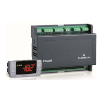
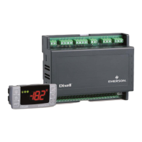
Controllers for multiplexed cabinets, suitable for applications on medium or low temperature. Can be inserted in a LAN.
Lists device names, descriptions, and Emerson part numbers for XM670 and XM679 models.
Lists the keys on the front panel of XM670-XM679 controllers and their functions.
Describes the function of each LED on the front panel of XM670-XM679 controllers.
Procedure to access the fast access menu by pressing the UP button.
Procedure to view the maximum and minimum recorded temperatures using the UP/DOWN buttons.
Steps to view and change the setpoint value using the SET button.
Instructions to initiate a manual defrost cycle by pressing the DEF key.
Guide to access the user-accessible parameters list (PR1).
Steps to access the protected parameter list (PR2) using a security code.
Procedure to assign a MODBUS address to the device using SET and DOWN buttons.
Steps to modify parameter values using the SET, UP, and DOWN buttons.
How to switch the controller ON/OFF using the ON/OFF key.
Parameters for setting energy saving cycle start and length during workdays and holidays.
Parameters for setting workday and holiday defrost start times for programmable defrost cycles.
Explains regulation performed based on temperature measured by the thermostat probe.
Describes standard and continuous regulation methods using hysteresis and PI regulators.
Details the standard ON/OFF regulation using the Hy parameter for differential.
Explains continuous regulation for XM679 using PI regulator with Hy and Int parameters.
Covers the defrost procedure, including starting and ending conditions.
Details conditions for starting defrost cycles, local or network initiated.
Explains how the defrost procedure is terminated based on probe temperatures.
Covers fan control modes via relay and analog output.
Details fan control modes (C-n, C-y, O-n, O-y) and the FSt parameter.
Explains modulating output for fans based on ASr, PbA, AMi, and AMA parameters.
Describes anti-sweat heater control with or without dewpoint information.
Explains how the auxiliary output is switched ON/OFF via digital input or DOWN key.
Configures a digital input for a generic alarm, signaling without affecting outputs.
Configures a digital input for a serious alarm, shutting down outputs.
Configures a digital input for a pressure switch, stopping compressor and regulation.
Configures a digital input for door status, affecting alarms and regulation.
Configures a digital input to start the defrost cycle.
Configures a digital input to turn the auxiliary relay ON/OFF.
Configures a digital input to turn the light relay ON/OFF.
Configures a digital input for remote ON/OFF control of the controller.
Configures a digital input to change regulation from cooling to heating and vice versa.
Function not used for changing regulation type.
Configures a digital input to change setpoint based on Energy Saving function.
Configures a digital input for holiday function, affecting Energy Saving and defrost cycles.
Explains digital input polarity configuration using I#P parameters (CL or OP).
Recommendations for mounting probes, especially thermostat and defrost termination probes.
Steps to download parameters from the Hot Key to the controller.
Steps to upload parameters from the controller to the Hot Key.
Alarm indication for internal check failure in memory data integrity.
Explains how probe alarms and temperature alarms automatically stop.
Baud rate, cable length, and I/O Net biasing recommendations for E2 to XM communication.
Specifies recommended Belden cable types for Analog Temp Sensor, Digital Input, RS-485, etc.
Wiring diagram for XM670 showing connections for ALL power supply and accessories.
Wiring diagram for XM679 with 230VAC valves, including hot key and input connections.
Wiring diagram for XM679 with 24VAC valves, including hot key and input connections.
Explanation of how a connected pressure transducer acts as the regulator on the LAN.
Describes values related to superheat control, including dPP, dP6, and SH.
Instructions for using the CX660 keyboard display, including terminal connections and distance limits.
Enables managing multiple defrosts simultaneously via LAN connection.
Details probe and transducer selection for superheat control configuration.
Describes the analog output connector and its use for controlling anti-sweat heaters.
Information on monitoring temperatures via RS485 network across controllers.
Details RS485 connection for sharing pressure transducers across multiple controllers on a LAN.
Steps to configure a pressure probe for sharing across the LAN, setting up master/slave devices.
Mapping of E2 COM ports to MODBUS communication for older E2 versions.
Mapping of E2 COM ports to MODBUS communication for newer E2 versions.
Steps to set up devices on the E2 for MODBUS communication.
Configuring E2 COM ports as MODBUS ports and setting communication parameters.
Procedure to add and address XM670-XM679 units to the E2 for communication.
Specifies recommended wire types for MODBUS communication, including Belden cable specs.
Instructions for using MODBUS termination blocks for XM670/XM679 devices.
| Input Voltage | 24 VDC |
|---|---|
| Output Voltage | 24 VDC |
| Protection Class | IP20 |
| Controller Type | PLC |
| Storage Temperature | -20°C to 70°C |
| Communication Protocol | Ethernet |