Do you have a question about the EMG 57-TW and is the answer not in the manual?
Overview of the 57-TW and 66-TW pickup models, including dimensions and coil modes.
Detailed electrical and physical specifications for 57-TW and 66-TW pickups.
General notes and advice for installing EMG pickups, including wiring and grounding.
Lists all the parts included in the EMG 57-TW/66-TW pickup set.
Details the warranty terms and conditions for EMG pickups and accessories.
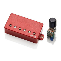
Explains how the push-pull switch selects between single-coil and dual-coil modes.
Provides diagrams for connecting the push-pull switch for different coil mode selections.
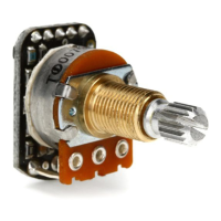
Outlines the four possible uses for the push-pull pot section (Volume/Tone).
Details how to wire the pot for Master Volume or Pickup Volume control.
Explains wiring the pot as a passive tone control for the pickup.
Details wiring the pot as a master tone control for the instrument.
Shows wiring for two pickups with one master volume and one master tone.
Wiring diagram for independent volume controls and a passive master tone.
Wiring diagram for independent volume and tone controls for both pickups.
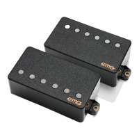
The EMG 57-TW/66-TW Set is a versatile pickup system designed for electric guitars, offering both single-coil and dual-coil modes to provide a wide range of tonal options. This set is part of EMG's Metalworks series, known for its active electronics and consistent performance. The "TW" in the model name signifies its "Two-Way" functionality, allowing users to switch between humbucking and single-coil sounds via a push-pull pot.
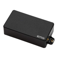
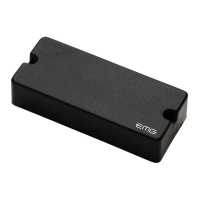
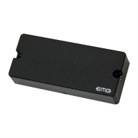
The EMG 57-TW and 66-TW are active humbucking pickups that can be switched into a single-coil mode. The 57-TW is typically used in the bridge position, while the 66-TW is designed for the neck position. Both pickups utilize active circuitry, which provides a high-output, low-noise signal, making them suitable for various musical genres, from clean jazz to high-gain metal.
In dual-coil (humbucking) mode, the pickups offer a full, powerful sound with excellent sustain and clarity, characteristic of EMG's active humbuckers. The 57-TW, with its Alnico/Steel magnet combination, delivers a classic PAF-like tone with a modern edge, featuring pronounced mids and a tight low end. The 66-TW, with its Ceramic/Steel magnets, provides a warm, articulate tone in the neck position, with rich harmonics and smooth highs.
When switched to single-coil mode via the included push-pull pot, the pickups emulate the brighter, snappier sound of traditional single-coil pickups. This allows guitarists to access a wider sonic palette without changing instruments. The single-coil mode is achieved by deactivating one of the coils within the humbucker, offering a distinct tonal contrast to the humbucking mode. The specific coils active in single-coil mode vary between the 57-TW and 66-TW: for the 57-TW, coils L2 and L3 are active, while for the 66-TW, coils L1 and L3 are active.
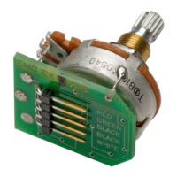
The system is designed for solderless installation, simplifying the setup process for most users. It includes all necessary components such as push-pull pots, tone controls, battery bus, output jack, and various cables, all designed to connect easily without soldering, except in specific cases like long panel output jacks or existing battery holders.
| Brand | EMG |
|---|---|
| Model | 57-TW |
| Category | Accessories For Music Instruments |
| Language | English |