RED WIRES
FROM PICKUPS
MASTER
VOLUME
OUTPUT
BATTERY
NEG (-) BLACK
B118
ACTIVE BALANCE
CONTROL
ACTIVE TONE
(VLPF)
9V+ POWER BUSS
NOTE REVERSED CONNECTORS
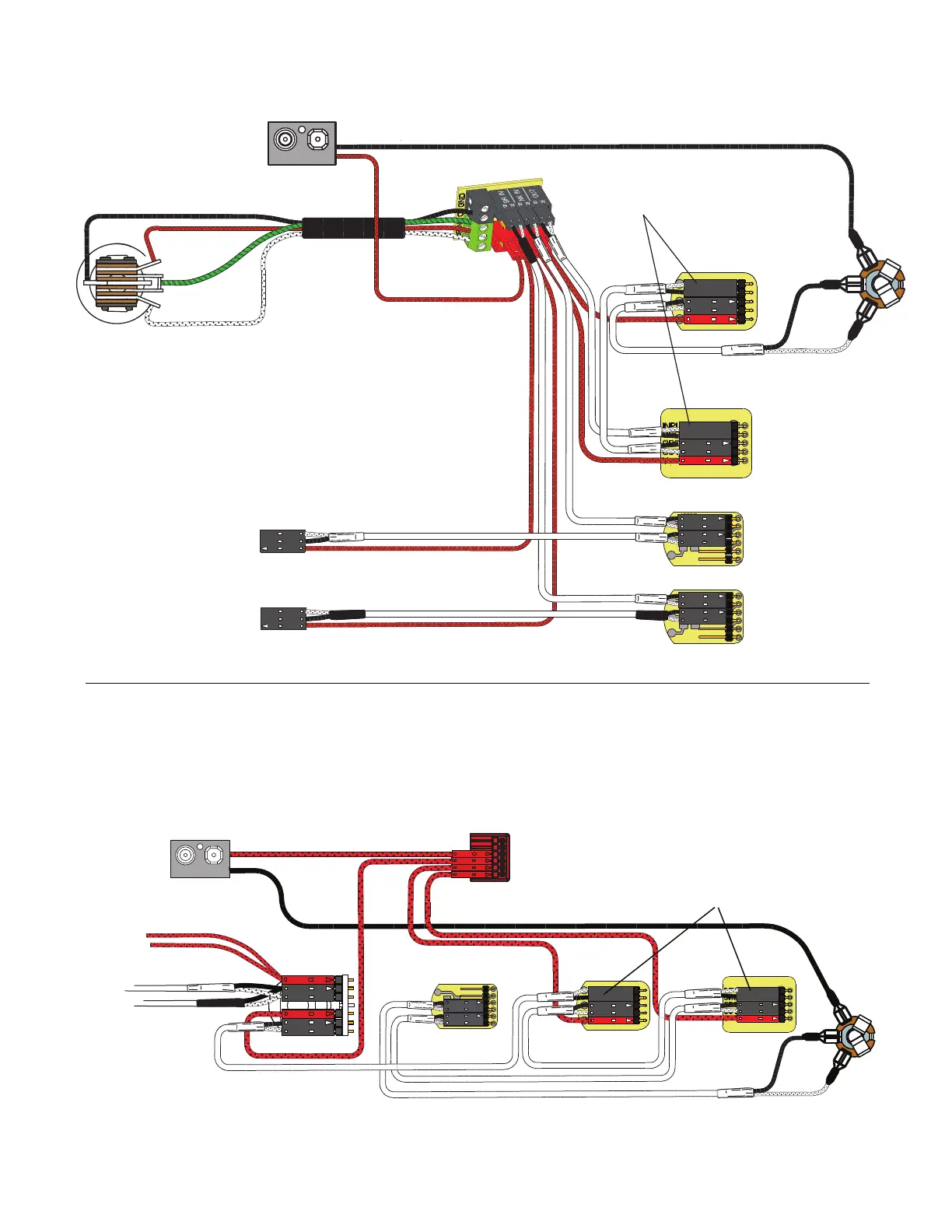
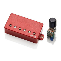
This diagram illustrates an installation using the X Series pickups from EMG
that have an active Tone control. The controls are wired in the above order with
the master Volume control last in the circuit. If you are using
the Active Balance Control remember that a passive Tone control will not
function when it comes after the ABC Control. If you want a standard tone
control the VLPF will be required.
RED
RED
RED
EMG Active Neck Pickup
(Upper 3 pin header)
EMG Active Bridge Pickup
(Lower 3 pin header)
EXB
CONTROL
BOTTOM
VIEW
T
R
S
- 9V +
VOLUME
B122rH
VOLUME
B122rH
RED
RED
RED
GROUND
BRIDGE P/U
NECK P/U
OUTPUT
VOLUME
B122rH
RED
EXB Page 4
Diagram #7
2 Pickups
Toggle Style Switch
Volume each Pickup (Volumes are independent)
EXB Control
Master Active Tone (VLPF)
Diagram #8
2 Pickups
ABC Control
Active Tone (VLPF)
EXB Control
Master Volume Control
Output Jack
OUTPUT
T
R
S
NK VOLUME
NECK PICKUP
BRIDGE PICKUP
BR VOLUME
BATTERY
NEG (-)
OUTPUT CABLE
NOTE:
REVERSED CONNECTORS
- 9V +
ACTIVE TONE
(VLPF)
EXB
CONTROL