Do you have a question about the Emheater EM12 Series and is the answer not in the manual?
Detailed safety instructions for installation, wiring, and operation.
General safety advice including motor insulation and thermal protection.
Explains the naming convention for EM12 series frequency inverters.
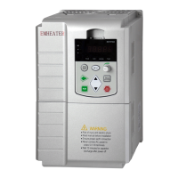
Describes the information found on the inverter's nameplate.
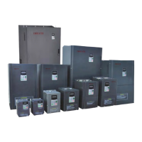
Lists models and technical data for the EM12 series.
Details the standard and functional specifications of the inverter.
Provides diagrams and dimensions for product appearance and installation.
Lists available optional accessories for the frequency inverter.
Outlines daily and regular inspection and maintenance procedures.
Specifies the warranty terms and conditions for the frequency inverter.
Guides the selection of appropriate braking resistors and units.
Specifies the recommended environmental conditions for inverter installation.
Details installation orientation and required clearances for proper ventilation.
Illustrates the connection of main circuit peripheral devices to the inverter.
Provides guidance on using main circuit peripheral devices with the inverter.
Recommends peripheral devices based on inverter model selection.
Explains how to remove and mount the operating panel and cover.
Describes the layout and purpose of the inverter's terminal connections.
Illustrates and describes the main circuit terminals for different models.
Warns about important considerations for main circuit wiring practices.
Details the control and main circuit terminals and their wiring.
Explains the operating panel indicators, display, and keys.
Describes how to navigate and change function codes in the menu.
Details how to view status parameters in stop and running states.
Explains how to set and manage the user password for protection.
Guides the process of motor auto-tuning for optimal performance.
Covers fundamental parameters like motor type and control mode.
Details parameters for controlling motor start and stop operations.
Explains auxiliary functions such as JOG, jump frequency, and time units.
Describes the configuration and functions of digital and analog input terminals.
Details the functions and configurations of digital and analog output terminals.
Explains parameters for pulse and analog input terminals, including calibration.
Covers parameters for pulse and analog output terminals, including FMP and AO functions.
Describes virtual DI/DO terminals and their state settings.
Details calibration parameters for analog inputs and outputs.
Explains keypad functions and LED display parameter settings.
Covers parameters for communication settings like Modbus protocol.
Lists fault types, causes, solutions, and protection parameters.
Details parameters for fault detection and logging.
Covers parameters related to motor overload and protection settings.
Explains PID control parameters for process automation.
Describes multi-function parameters for speed and PID source selection.
Details parameters for the simple PLC function, including running modes and segments.
Covers parameters for swing frequency and counting.
Lists motor nameplate parameters and auto-tuning settings for Motor 1.
Covers vector control parameters for Motor 1, including PI gains.
Details V/F curve settings and parameters for Motor 1.
Refers to Motor 1 parameters for setting Motor 2.
Covers parameters for carrier frequency, PWM modulation, and SVC modes.
Lists parameters for monitoring inverter status.
Covers system parameters like password and default settings.
Defines electromagnetic compatibility and its importance.
Describes EMC requirements and test methods according to international standards.
Provides guidance on handling harmonic effects and electromagnetic interference.
Lists common faults, possible causes, and their solutions.
Provides a troubleshooting table for common inverter faults.
Defines the Modbus serial communication protocol and its use.
Explains how the inverter connects to a Modbus network.
Describes the hardware interface, topological mode, and transmission modes.
Lists standard parameters with their codes, settings, defaults, and properties.
Lists basic function parameters for the inverter.
Lists parameters for controlling motor start and stop.
Lists auxiliary function parameters like JOG and jump frequency.
Lists parameters for configuring digital input terminals.
Lists parameters for configuring output terminals like FMR and DO.
Lists parameters for pulse and analog input terminals.
Lists parameters for pulse and analog output terminals.
Describes virtual DI/DO terminals and their state settings.
Details calibration parameters for analog inputs and outputs.
Explains keypad functions and LED display parameter settings.
Lists parameters for communication settings.
Lists fault and protection parameters.
Details parameters for fault diagnosis.
Lists parameters for motor protection.
Explains PID control parameters for process automation.
Describes multi-function parameters for speed and PID source selection.
Details parameters for the simple PLC function, including running modes and segments.
Covers parameters for swing frequency and counting.
Lists motor 1 parameters and auto-tuning settings.
Lists vector control parameters for Motor 1.
Lists V/F control parameters for Motor 1.
Covers parameters for carrier frequency, PWM modulation, and SVC modes.
Lists parameters for monitoring inverter status.
Covers system parameters like password and default settings.