Do you have a question about the Emheater EM15 Series and is the answer not in the manual?
Check the inverter before unpacking and read the manual carefully for first-time use.
EM15 series frequency inverter complies with IEC/EN61800 standards and has CE certification.
Parameters are listed in Appendix II for reference.
Explanation of danger and warning symbols used in the manual for safety.
Essential safety information for installation, wiring, and operation to prevent injury or damage.
Covers motor insulation testing, thermal protection, wiring best practices, and input voltage limits.
Includes advice on surge suppression, altitude, scrap disposition, and motor compatibility.
Explains the labels and designation rules for EM15 series frequency inverters.
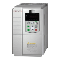
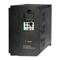
Details the physical appearance and installation dimensions of EM15 models.
Specifies input/output voltage, frequency, control modes, and technical performance metrics.
Describes built-in functions like PLC, PID, AVR, and external interface capabilities.
Outlines the installation environment, temperature, humidity, and storage conditions.
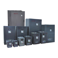
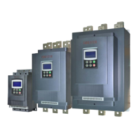
Provides dimensions for wall-mounted installation of EM15 series inverters by power class.
Lists daily inspection items for frequency inverters to ensure proper operation and longevity.
Details regular inspection points, including air ducts, screws, corrosion, and wiring terminals.
Information on service life of vulnerable parts and guidelines for frequency inverter storage.
Guidance on selecting the appropriate resistance value and power for braking resistors.
Specifies requirements for the installation location, temperature, humidity, and ventilation.
Provides guidance on inverter orientation, ventilation space, and mounting for optimal performance.
Illustrates the connection diagram for peripheral devices with the frequency inverter.
Provides instructions for using main circuit peripheral devices like MCCB and RCCB.
Instructions for safely removing and mounting the operating panel or keypad.
Steps for removing and mounting the upper cover of the frequency inverter's case.
Details the layout and function of control and main circuit terminals.
Explains the function and description of main circuit terminals for various inverter models.
Cautions for power supply wiring, motor wiring, and cable length considerations.
Guidance on proper grounding and methods to solve conduction/radiation interference.
Presents wiring diagrams for control and main circuits.
Illustrates the layout of control circuit terminals for different inverter models.
Details the function of each key and display area on the operating keypad.
Explains the three-level menu structure for viewing and modifying function codes.
Describes how to display and monitor various status parameters during operation and stop.
Details the user password protection feature and how to set or cancel it.
Step-by-step guide for performing motor auto-tuning for optimal control performance.
Configures motor type (AC asynchronous) and motor control mode (SVC, V/F, FVC).
Determines the input channel for control commands: keypad, terminals, or communication.
Sets the primary channel for frequency setting from digital, analog, pulse, or communication.
Configures the secondary channel for frequency setting, used in conjunction with the main source.
Defines the range of auxiliary frequency and logic for source selection and calculation.
Sets digital frequency parameters and whether to record settings after power failure.
Configures maximum frequency, upper/lower limits, and offsets for frequency control.
Sets acceleration/deceleration modes (Linear, S-curve) and time parameters.
Configures start modes: direct, speed tracking, or pre-excited start.
Defines modes for rotational speed tracking restart to ensure smooth motor startup.
Configures parameters for JOG running, including frequency, acceleration, and deceleration times.
Sets parameters for DC braking during stopping, including initial frequency and current.
Manages multiple acceleration/deceleration time groups and frequency jump settings.
Configures frequency switchover points and enables/disables reverse running.
Sets running mode for low frequency, droop control for load balancing, and JOG priority.
Configures dormant/wakeup functions for water supply applications and timing functions.
Assigns functions to digital input (DI) and high-speed pulse (HDI) terminals.
Selects functions for FMP, Relay 1, Relay 2, and describes available output terminal functions.
Details output terminal functions (e.g., frequency reached, fault output) and sets delay times.
Configures frequency detection values, hysteresis, detection width, and current detection parameters.
Sets parameters for detecting when the output frequency reaches specific values or ranges.
Configures settings for zero current detection and over current output detection.
Sets parameters for detecting when the output current reaches specific values or ranges.
Configures parameters for pulse input (HDI), including minimum/maximum input and filter time.
Sets voltage limits for AI inputs and defines AI input curves for voltage/current mapping.
Configures the function of FMP, AO1, and AO2 output terminals for various signals.
Assigns functions to virtual digital input (VDI) terminals, similar to DI terminals.
Configures virtual digital output (VDO) functions for logic control with VDI terminals.
Configures the function of the MF.K key and the STOP/RESET key.
Sets which running or stopping parameters are displayed on the LED indicators.
Configures communication type, baud rate, data format, and broadcast address for Modbus.
Configures motor overload protection selection, gain, and pre-warning coefficient.
Sets parameters for fault auto reset times, relay action, and fault auto reset time interval.
Configures input/output phase loss protection, contactor energizing protection, and off load protection.
Sets parameters for detecting over-speed conditions and too large speed deviation.
Configures actions for instantaneous power failure, including deceleration and voltage restoring.
Sets the overvoltage and under voltage thresholds for frequency inverter protection.
Defines actions for various faults like motor overload, phase loss, and communication errors.
Configures fault protection actions for user-defined faults and running modes after faults.
Records and displays the types of recent faults, including frequency, current, and voltage.
Configures PID setting source, digital setting, and PID feedback source.
Sets PID action direction (forward/reverse) and the range for PID setting/feedback.
Configures proportional (Kp), integral (Ti), and differential (Td) parameters for PID control.
Sets PID parameter switchover conditions based on deviation or DI terminals, and integral properties.
Configures PID initial values, holding time, deviation limits, and differential output range.
Defines multi-function parameters for various applications like V/F separation and PID.
Configures simple PLC running modes and record settings for power failure and stopping.
Parameters for constant pressure water supply applications, including pressure and sleep settings.
Sets essential motor parameters like power, voltage, current, frequency, and speed for auto-tuning.
Configures speed/torque control mode and PI gains for vector control loops.
Selects V/F curves (Linear, Square, multi-point) and configures torque boost settings.
Adjusts carrier frequency to optimize motor noise, interference, and temperature.
Displays real-time parameters like frequency, voltage, current, DI/DO status, and motor temperature.
Configures user password protection and parameter modification properties.
Adjusts current limit levels, voltage limits, and related gain/threshold parameters.
Details EMC standards (IEC/EN61800-3) and provides guidance on harmonic effects and interference.
Provides precautions for installation and handling electromagnetic interference.
Lists common faults (Err01-Err23) with possible causes and recommended solutions.
Explains the Modbus protocol, its application methods, and bus structure.
Details the data structure, frame format, and command codes for Modbus RTU communication.
Lists standard parameters for Motor Type, Control Mode, Command Source, and Frequency Sources.
Details parameters for start modes, speed tracking, DC braking, and stop modes.
Covers JOG settings, DC braking, jump frequencies, reverse running, and dormant/timing functions.
Configures functions for digital inputs (DI), HDI, and virtual DI/DO terminals.
Defines functions for FMP, relay, and DO output terminals, including delay times.
Sets parameters for pulse and analog input terminals, including voltage limits and curves.
Configures functions for FMP, AO1, and AO2 output terminals.
Sets functions for virtual digital input and output terminals for logic control.
Configures keypad functions and LED display parameters for running and stopping states.
Sets Modbus communication parameters like baud rate, data format, and response delay.
Configures fault protection settings for motor overload, phase loss, over-speed, and power failure.
Provides information on recording and diagnosing fault types and their parameters.
Sets parameters for motor protection, including overcurrent alarm and delay.
Configures PID control settings, including sources, gains, and switchover conditions.
Defines multi-function parameters and their sources for various control applications.
Configures simple PLC running modes, segment times, and recording options.
Parameters for constant pressure water supply applications, including pressure and sleep settings.
Details motor parameters for asynchronous and synchronous motors, essential for auto-tuning.
Configures parameters for vector control, including speed/torque control and current loops.
Sets V/F curve types, torque boost, slip compensation, and oscillation suppression.
Adjusts carrier frequency and PWM modulation modes for control optimization.
Monitors frequency inverter running state, including frequency, voltage, current, and DI/DO status.
Configures system parameters like user password, product number, and software version.
Adjusts current limit, voltage limit, and slip compensation parameters for control optimization.