Do you have a question about the EMKO ESM-1510-N and is the answer not in the manual?
Details the electrical supply, input types, and output configurations for the ESM-1510.
Provides a table of codes and options for customizing and ordering the ESM-1510.
Outlines the two-year warranty period and conditions for the temperature controller.
Offers guidance on proper cleaning and repair procedures for the device.
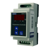
Provides a general overview of the ESM-1510 unit and its purpose.
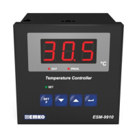
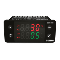
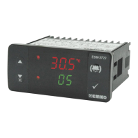
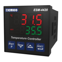
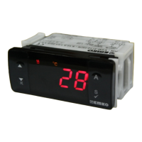
Illustrates the front panel features and dimensions of the temperature controller.
Specifies the operating temperature, humidity, altitude, and forbidden environments.
Details the step-by-step procedure for mounting the unit on a DIN rail.
Explains the safety precautions and steps for detaching the unit from the rail.
Shows the device's terminal layout and provides instructions for making electrical connections.
Presents the comprehensive wiring diagram for connecting sensors, power, and outputs.
Displays example device labels illustrating different input and output configurations.
Guides on connecting the appropriate supply voltage, including fuse and switch recommendations.
Details how to connect TC, PTC, NTC, PT-100, and PT-1000 sensors correctly.
Lists the test values for galvanic isolation between various circuits of the controller.
Explains the wiring for both relay output and SSR driver output options.
Describes how the software revision number is displayed upon initial power-up.
Details the procedure for adjusting and confirming the temperature set value.
Explains various programmable parameters for configuring device behavior.
Illustrates operational graphics showing temperature, set value, and output states.
Provides a flowchart for navigating and accessing programming mode parameters.
Guides on how to enter programming mode, modify parameters, and save changes.
| Temperature Range | -50 to 150°C |
|---|---|
| Input Type | Thermocouple, RTD |
| Control Algorithm | PID |
| Power Supply | 230V AC |
| Output | Relay, SSR |
| Dimensions | 48 x 48 x 100 mm |
| Mounting | Panel mounting |