Do you have a question about the emmeti MIRAI SMI and is the answer not in the manual?
Key characteristics of the heat pump, including technology and efficiency.
Details on efficient components, inverter drive, and electronic management system.
Information on accessing components for installation and maintenance.
List of included accessories like manuals and fittings.
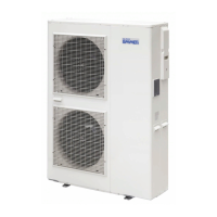
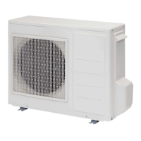
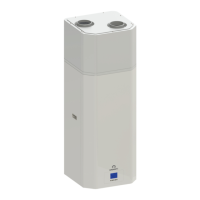
Identification of major components for EH0618DC, EH1018DC, and EH1218DC/EH1618DC/EH1718D3 models.
Technical drawings showing dimensions for EH0618DC, EH1018DC, and EH1218DC/EH1618DC/EH1718D3 models.
List of relevant European directives the product complies with.
Detailed technical specifications for heating/cooling with various units and panels.
Performance graphs for circulator flow rate, prevalence, and power for different models.
Graphical representation of heating/cooling operating ranges by air/water temperatures.
Information on product packaging, labels, symbols, dimensions, and weight.
Explanation of the rating label, its contents, and an example.
Safety instructions for moving units with a forklift and warnings about handles.
Instructions and warnings for safely unpacking the unit.
Safety info for R32: first aid, firefighting, physical/chemical properties, disposal, and installation limits.
General warnings, meanings of symbols, prohibitions, and safety notes.
Guidelines on authorized personnel and prohibitions for installation locations.
Required clearance around the unit for maintenance access.
Instructions for securely fixing the unit and considerations for heavy snowfall.
Guidance on installing condensate drainage pipes correctly.
Details of hydraulic connections, including system scheme and recommendations.
Explanation of anti-freeze function and water quality requirements.
Procedures for filling the hydraulic circuit with water and purging air.
Safety precautions and guidelines for electrical system and power supply.
Instructions for connecting power cables to terminal block, including safety.
Diagram showing factory electrical connections to the PCB terminal block.
Specs for connecting sensors and remote controls to the PCB terminal block.
Specs for connecting components to the PCB terminal block using 230V.
Checklist for installation verification and procedures for test operation.
Overview of the SMART-MT display and its main screen functions and indicators.
Explanation of how to use the function keys for navigation and control.
Step-by-step guide for setting the clock on the SMART-MT controller.
Procedure for accessing parameter settings using a password.
Description of the "Set" menu and its sub-menus for heat pump parameters.
Guide on how to access and modify parameters within the "Set" menu.
Detailed list of parameters within the "Set" menu (labels, ranges, defaults).
Continuation of "Set" menu parameters, covering DHW and other settings.
Final "Set" menu parameters, including EHS, PUMP, and AL labels.
Description of the "Prg" menu and its sub-menus for advanced parameters.
Guide on how to access and modify parameters within the "Prg" menu.
Detailed list of "Prg" parameters for cooling/heating set points and climatic curves.
Continuation of "Prg" parameters, including antifreeze settings and time bands.
How to check and control the heat pump's ON/OFF status via SMART-MT or external contact.
Explanation of the activation of the heat pump circulator (Pump 1).
Information on connecting and activating a booster pump.
Ways to change the heat pump's operating mode (Cooling/Heating).
How to activate "Night Mode" to reduce compressor noise and capacity.
How to activate a second set point for air terminal units.
How climatic curves regulate water temperature based on external conditions.
How SMART-MT controls inverter frequency based on temperature errors.
How to activate a dehumidifier for room humidity control.
How to manage DHW production by connecting the heat pump to an accumulation tank.
Setting comfort and attenuation periods using the CRONO-TH.
How to manage heat with an auxiliary generator (bivalent system).
How SMART-MT manages high and low-temp systems simultaneously.
How to enable and configure anti-freeze protection within the SMART-MT controller.
Importance of the outdoor air temp sensor and connecting a remote probe.
Common troubleshooting steps for incorrect unit operation.
List of alarm codes, causes, and solutions for the SMART-MT.
Procedure for manually resetting protection status after alarms.
How the system requests an alternative heat source when the heat pump is insufficient.
Safety precautions and instructions for cleaning the heat pump.
How to check the proper drainage of condensation water.
Information regarding the disposal of electrical and electronic equipment.
Guidelines for disposing of packaging materials responsibly.
Wiring diagram for the EH0618DC model, showing electrical connections.
Wiring diagram for the EH1018DC model, detailing electrical connections.
Wiring diagram for the EH1218DC model, showing electrical connections.
Wiring diagram for the EH1618DC model, detailing electrical connections.
Wiring diagram for the EH1718D3 model, showing electrical connections.
General terms and conditions of the product warranty.
Form for the end-user to fill out for warranty registration.
Form for the distributor to fill out for warranty registration.
Form for the installer to fill out for warranty registration.