EasyManua.ls Logo

emmeti EH0618DC User Manual

emmeti EH0618DC
168 pages
Go to English
To Next Page IconTo Next Page
Page #1 background imageLoading...
Page #1 background image
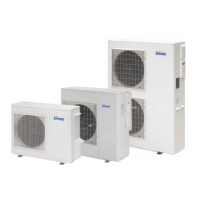
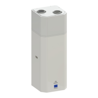
MIRAI - SMI 4.0
System Manager Integrated
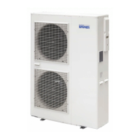
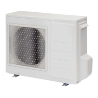
EH0618DC / EH1018DC / EH1218DC / EH1618DC / EH1718D3
Rev. G - 03.2022
MANUALE INSTALLAZIONE ED USO
IT
INSTALLATION AND USE MANUAL
GB

Questions and Answers:

emmeti EH0618DC Specifications

General IconGeneral
Brandemmeti
ModelEH0618DC
CategoryHeat Pump
LanguageEnglish

Summary

Product Introduction

Unit Dimensions

Details the physical dimensions of the unit.

Conformity to European Directives

Lists relevant European directives and their numbers for compliance.

Technical Specifications

Technical Data Overview

Presents detailed technical specifications for various models and applications.

Technical Specifications

Circulator Performance Curves

Explains circulator speed levels and provides flow rate/power graphs for models.

Technical Specifications

Operating Range Charts

Shows graphical representations of heating and cooling operating ranges based on air and water temperatures.

Movement and Transport

Packing and Handling Instructions

Describes packaging details, handling symbols, and packing dimensions for different models.

Movement and Transport

Unit Identification and Unpacking Procedures

Explains the unit's rating label and details the unpacking process and safety.

Warnings

Refrigerant R32 Safety Data Sheet Extract

Provides safety information, first aid, firefighting, and exposure control for R32 refrigerant.

Warnings

General Safety Instructions and Prohibitions

General warnings, prohibited actions, and safety symbol meanings for installation and use.

Installation Prohibitions and Warnings

Specifies prohibitions and warnings related to the installation process.

Installation

Unit Installation Requirements and Spaces

Details minimum operating spaces, fixing methods, and condensate drainage pipes.

Installation

Hydraulic System Connections and Recommendations

Explains hydraulic connections, provides a system scheme, and gives recommendations for the circuit.

Installation

Operation Warnings and Anti-Freeze Protection

Crucial warnings for operation, anti-freeze function, and water quality requirements.

Installation

Hydraulic Circuit Water Charge and Air Purge

Step-by-step instructions for filling the hydraulic circuit and removing air.

Installation

Electrical System Safety and Connections

Provides instructions and warnings for electrical connections and safety, including earthing.

Installation

Wiring Connections to Terminal Blocks

Detailed instructions on connecting wiring to terminal blocks, including cautions.

Installation

Recipe 1 Electrical Connection Details

Details electrical connections for Recipe 1 configuration, showing diagrams and terminal block assignments.

Installation

Recipe 1 Configurable Parameters and PCB Connections

Lists configurable parameters for Recipe 1 and specifies PCB connections for probes and inputs.

Installation

Recipe 2 Electrical Connection Details

Details electrical connections for Recipe 2 configuration, showing diagrams and terminal block assignments.

Installation

Recipe 2 Configurable Parameters and PCB Connections

Lists configurable parameters for Recipe 2 and specifies PCB connections for probes and inputs.

Installation

Recipe 3 Electrical Connection Details

Details electrical connections for Recipe 3 configuration, showing diagrams and terminal block assignments.

Installation

Recipe 3 Configurable Parameters and PCB Connections

Lists configurable parameters for Recipe 3 and specifies PCB connections for probes and inputs.

Installation

Recipe 10 Electrical Connection Details

Details electrical connections for Recipe 10 (Febos-Crono Master) configuration.

Installation

Recipe 10 Configurable Parameters and PCB Connections

Lists configurable parameters for Recipe 10 and specifies PCB connections for probes and inputs.

Installation

Recipe 13 Electrical Connection Details

Details electrical connections for Recipe 13 (ECO HYDRO KIT) configuration.

Installation

Recipe 13 Configurable Parameters and PCB Connections

Lists configurable parameters for Recipe 13 and specifies PCB connections for probes and inputs.

Type of Installation

Diagram 1 Hydraulic Connection

Shows the hydraulic connection diagram for Radiant system + Fancoil + Eco Hot Water.

Type of Installation

Diagram 1 Electrical Connection

Shows the electrical connection diagram for Recipe 1.

Type of Installation

Diagram 2 Hydraulic Connection

Shows the hydraulic connection diagram for Radiant system + Fancoil + Boiler x DHW.

Type of Installation

Diagram 2 Electrical Connection

Shows the electrical connection diagram for Recipe 1.

Type of Installation

Diagram 3 Hydraulic Connection

Shows the hydraulic connection diagram for Radiant system + Fancoil + ECO HYDRO KIT + Boiler.

Type of Installation

Diagram 3 Electrical Connection

Shows the electrical connection diagram for Recipe 2.

Type of Installation

Diagram 4 Hydraulic Connection

Shows the hydraulic connection diagram for Radiant system + Fancoil + ECO HYDRO KIT + Boiler + FEBOS-CHRONO + DEHUMIDIFIER.

Type of Installation

Diagram 4 Electrical Connection

Shows the electrical connection diagram for Recipe 10.

Thermal Adjustment "SMART MT"

Controller Display and Key Functions

Explains the Smart-MT controller's display, keys, and their functions.

Thermal Adjustment "SMART MT"

Smart-MT Key Operations and Password Setting

Details key operations in the main screen and the procedure for setting the password.

Thermal Adjustment "SMART MT"

Setting Menu Parameter Access

Guides on accessing and changing parameters within the "Set" menu.

Thermal Adjustment "SMART MT"

SMART-MT Time and Date Configuration

Provides instructions for setting the date and time on the Smart-MT controller.

Thermal Adjustment "SMART MT"

Service Parameters: Remote Consents and Inputs

Lists service parameters related to remote consents and analogue inputs.

Thermal Adjustment "SMART MT"

Service Parameters: Ambient Settings, Signals, and Outputs

Lists service parameters for ambient settings, signals, and physical output status.

Thermal Adjustment "SMART MT"

Service Parameters: Heat Pump Status, Counters, and Configurations

Lists service parameters for heat pump status, counters, and system configurations.

Thermal Adjustment "SMART MT"

Service Parameters: System Configurations (continued)

Lists service parameters for system configurations, including heat pump settings.

Thermal Adjustment "SMART MT"

Service Parameters: Compressor Frequency Adjustment Settings

Lists service parameters for water temperature settings for compressor frequency adjustment.

Thermal Adjustment "SMART MT"

Service Parameters: Ambient Signals and Compressor Steps

Lists service parameters for ambient settings, signals, and compressor steps.

Thermal Adjustment "SMART MT"

Service Parameters: DHW, Frost Protection, Additional Heater

Lists service parameters for DHW production, frost protection, and additional heater settings.

Thermal Adjustment "SMART MT"

Service Parameters: Alarm History

Lists service parameters for alarm history.

User Section: Operation

Heat Pump ON/OFF Control

Explains how to turn the heat pump on and off using the Febos-Crono system.

Operating Mode Selection (Heating/Cooling)

Describes how to select heating or cooling mode via Febos-Crono.

Ambient Thermostat Consent Function

Explains how ambient thermostat consent affects heat pump operation.

User Section: Operation

Water Temperature and Climate Curve Settings

Guides on setting water temperatures and adjusting them using climate curves.

Set Point 2 and Fancoil Consent Configuration

Explains how to set consent for Set Point 2 and Fancoil operation.

Circulator Activation Logic

Details when the heat pump circulator is activated automatically.

User Section: Operation

Compressor Modulation and Frequency Limitation

Explains compressor modulation and how to limit frequency via external signal.

Domestic Hot Water Heating Methods

Details how to heat domestic hot water using the heat pump or Eco Hot Water.

User Section: Operation

DHW Heating Configurations

Instructions for DHW heating with Eco Hot Water, Heat Pump, PdC addition, and electric heater.

User Section: Operation

Relaunch Circulator and Additional Heater Management

Explains relaunch circulator function and how the heat pump manages additional heater consent.

User Section: Operation

Heat Pump Operation Modes (Parallel, Alternate, Alarm)

Explains parallel, alternate, and alarm-driven operation with additional generators.

User Section: Operation

Frost Protection and External Sensor Settings

Explains frost protection mechanisms and the importance of the external temperature sensor.

Water Flow Rate Monitoring and Flow Meter Connections

Explains water flow rate monitoring, alarms, and connections for different flow meters.

User Section: Operation

Electrical Power Monitoring and Dehumidifier Operations

Covers electrical power monitoring and various dehumidifier operation modes.

User Section: Operation

Active Alarms, History, and System Alarm Inputs

Guides on accessing alarms, history, and configuring system alarm inputs.

Alarm Codes on SMART-MT

General Troubleshooting Guide

Provides a troubleshooting guide for common issues and checks.

Alarm Codes on SMART-MT

SMART-MT Alarm Codes and Solutions

Lists alarm codes, their descriptions, and corresponding solutions.

Manual Protection Status Reset Procedure

Explains how to manually reset protection status after an alarm.

Codes and Alarms on PCB Display

PCB Alarm Codes and Troubleshooting Steps

Lists alarm codes displayed on the PCB and their troubleshooting steps.

Codes and Alarms on PCB Display

PCB Error Codes: Temperature, Current, CT Disconnect Issues

Lists error codes related to discharge temperature, current, and CT disconnect.

Codes and Alarms on PCB Display

PCB Error Codes: Compressor, Sensors, Fuses

Lists error codes related to compressor rotation, sensors, and fuses.

Codes and Alarms on PCB Display

PCB Error Codes: Fan Motors, PCB, Installation

Lists error codes related to motor fans, PCB errors, and installation.

Codes and Alarms on PCB Display

PCB Error Codes: SMART-MT Serial, Power, Temperature Sensors

Lists error codes for SMART-MT serial error, power supply, and temperature sensors.

Codes and Alarms on PCB Display

PCB Error Codes: High Pressure, Compressor Over-temp, Cooling/Heating

Lists error codes for high pressure switch, compressor over-temperature, and cooling/heating issues.

Service and Maintenance

PCB Electrical Checks

Explains how to perform voltage, resistance, and continuity checks on the main PCB.

Service and Maintenance

Fuse Continuity and Fan Motor Voltage Checks

Illustrates how to check fuse continuity and measure fan motor voltage on the main PCB.

Service and Maintenance

Fan Motor and Pump Voltage Checks

Provides diagrams for measuring fan motor and pump voltages on the main PCB.

Service and Maintenance

Component Resistance Checks

Illustrates how to check the resistance of 4-way valves, defrost heater, and compressor.

Service and Maintenance

PCB Error History and Data Display Methods

Explains how to display and delete historical errors and access data display mode.

Temperature Sensor Electrical Characteristics

Provides resistance values for various temperature sensors at different temperatures.

Cleaning

Heat Pump Cleaning Procedures

Provides warnings and instructions for cleaning the heat pump, including what not to use.

Water Condensate Drainage Check

Explains how to check water condensate drainage and when to contact service.

Wiring Diagrams

EH0618DC Wiring Diagram

Wiring diagram for the EH0618DC model, showing PCB connections and safety warnings.

Wiring Diagrams

EH1018DC Wiring Diagram

Wiring diagram for the EH1018DC model, showing PCB connections and safety warnings.

Wiring Diagrams

EH1218DC Wiring Diagram

Wiring diagram for the EH1218DC model, showing PCB connections and safety warnings.

Wiring Diagrams

EH1618DC Wiring Diagram

Wiring diagram for the EH1618DC model, showing PCB connections and safety warnings.

Wiring Diagrams

EH1718D3 Wiring Diagram

Wiring diagram for the EH1718D3 model, showing PCB connections and safety warnings.

Product Fiche

EH0618DC + ITM-200 B Product Fiche

Product fiche details for EH0618DC model, including energy efficiency and technical data.

Product Fiche

EH1018DC + ITM-200 B Product Fiche

Product fiche details for EH1018DC model, including energy efficiency and technical data.

Product Fiche

EH1218DC + ITM-200 B Product Fiche

Product fiche details for EH1218DC model, including energy efficiency and technical data.

Product Fiche

EH1618DC + ITM-200 B Product Fiche

Product fiche details for EH1618DC model, including energy efficiency and technical data.

Product Fiche

EH1718D3 + ITM-200 B Product Fiche

Product fiche details for EH1718D3 model, including energy efficiency and technical data.

General Terms of Warranty

Warranty Coverage and Exclusions

Details warranty coverage, exclusions for negligence, improper installation, and wear.

Warranty Claims and Procedures

Covers reporting faults, replacement units, and payment terms related to warranty.

Related product manuals