Do you have a question about the emmeti Mirai SMI EH0614DC and is the answer not in the manual?
| Model | Mirai SMI EH0614DC |
|---|---|
| Energy Efficiency Class | A++ |
| Refrigerant | R32 |
| Power Supply | 230V/1Ph/50Hz |
| Power Input Cooling | 1.4 kW |
| Type | Air to Water |
| Heating Capacity | 6 kW |
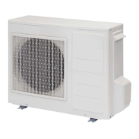
Key features and benefits of the heat pumps, including inverter technology and reliability.
Details on efficient components like large batteries, twin rotary compressors, and impulse modulating valve.
Information on accessing electrical panels, cooling circuits, and hydraulic units for ease of service.
Lists included accessories such as the Instructions Manual and condensate drainage fitting.
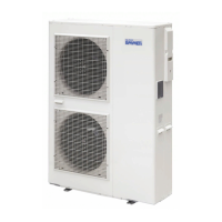
Diagram and labels of key components of the EH0614DC model.
Lists relevant EU directives for electromagnetic compatibility, low voltage, WEEE, and RoHS.
General safety warnings, symbols meaning, and precautions for unit installation and use.
Graphs showing the relationship between water flow and head for different models.
Charts illustrating the operating ranges for heating and cooling based on air and water temperatures.
Explains packaging labels, symbols, and provides a table of packing dimensions and gross weight.
Instructions on how to move the unit, emphasizing forklift use and avoiding handles.
Guidance on unwrapping, checking for damage, and contacting transport companies if issues arise.
Crucial safety warnings for installation, stressing the need for qualified technicians and proper procedures.
Guidelines for selecting an optimal installation site, considering stability, environment, and airflow.
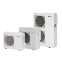
Detailed diagrams showing the dimensions and connection points for EH0614DC, EH1014DC, and EH1314DC/EH1614DC models.
Illustration showing required clearance space around the EH1614DC and EH1314DC units for proper operation.
Details on condensate drainage pipe requirements and water quality limits.
Example schema for system water connections and important notes on water quality and expansion tanks.
Details on hydraulic circuit, pipe isolation, filling, air discharge, and anti-freeze measures.
Instructions for electrical connections, including safety precautions and earthing cable requirements.
Diagrams and specifications for connecting internal and external PCB terminal blocks.
Checklist for installation verification and steps for test operation, including final verification.
Explanation of the SMART-MT regulator's display, icons, and button functions for operation.
Details on short and prolonged key presses for navigating menus and controlling functions.
Step-by-step guide for setting the clock on the SMART-MT regulator.
Instructions on how to access and set the password for advanced parameters.
Overview of menus within the "Set" menu, including HP, SEns, di, dEHU, SAni, EHS, AL.
Detailed list of "Set" menu parameters, including labels, ranges, defaults, and addresses.
Continuation of the "Set" menu parameters, covering dEHU, SAni, EHS sections.
Further continuation of "Set" menu parameters, including CYCA, SEtA, tiMA, HouA, OPEr, SEto, dELt, and alarm codes.
Introduction to the "Prg" menu, listing its sub-menus like USYS, FrEq, LOUU, AFR, P1, P2, dAYS.
Detailed list of "Prg" menu parameters for USYS section, covering temperature set points and climatic curves.
Detailed list of "Prg" menu parameters for USYS, FrEq, LOUU sections, related to water temperatures and compressor frequency.
Detailed list of "Prg" menu parameters for P1, P2, dAYS sections, related to timer profiles and weekday assignments.
Explanation of how the heat pump's ON/OFF state is controlled via the SMART-MT or CRONO-TH.
Details on how Pump 1 and Pump 2 are activated, including external commands and relay logic.
Describes the three methods for changing the heat pump's operation mode.
How to activate "Night Mode" to reduce compressor frequency, noise, and absorption.
How to activate a second set point for water delivery temperature, typically for air terminal units.
Explanation of how climatic curves determine requested water temperature based on external environment.
How the inverter frequency is controlled based on water temperature errors.
Importance of sensor placement and connection of a remote probe.
Management of DHW heating, including sensor connection and request methods.
Automatic management of electric heater for DHW integration based on temperature sensor.
How to operate the dehumidifier based on ambient humidity and cooling mode.
Explanation of the room thermostat output linked to CRONO-TH for air conditioning control.
Setting comfort and attenuation periods using CRONO-TH for energy saving.
Managing bivalent systems with an auxiliary generator for DHW production during low temperatures.
Usage of the 0-10V valve for systems with "HIGH" and "LOW" temperature circuits.
How the antifreeze function works and advice for cold environments.
Safety precautions and methods for cleaning the heat pump, including what not to use.
Procedure to check proper drainage of condensation water and when to contact service.
Common operating issues and checks to perform before requesting service.
Table listing alarm codes, their causes, and recommended solutions.
Table detailing error codes, appearance, method of check, and problem resolution for PCB errors.
How to display and delete error logs from the unit.
Steps to access and view monitored data from the unit's display.
Electrical schematic for the EH0614DC model.
Electrical schematic for the EH1014DC model.
Electrical schematics for the EH1614DC and EH1314DC models.
Information on fluorinated greenhouse gases and WEEE directive compliance.
Guidelines for safely disposing of old air conditioners, emphasizing refrigerant and recycling.
Instructions for disposing of packing materials responsibly.
Details on the terms and conditions of the product guarantee.