6
GB | Wireless Weather Station
Specications:
clock controlled by DCF radio signal
indoor temperature: 0 °C to +50 °C
outdoor temperature: -20 °C to +60 °C
temperature resolution: 0.1 °C
temperature measurement accuracy: ±2 °C
indoor humidity: 20 to 95 % RH
humidity resolution: 1 % RH
humidity measurement accuracy: ±5 % RH
bar. pressure measurement range: 900 hPa to 1,050 hPa
wireless sensor: transmission frequency 433 MHz, 3 mW e.r.p. max.
radio signal range: up to 60 m in an open area
number of sensors for connection: max. 3
power supply:
main station: 3× 1.5 V AAA batteries (not included)
sensor: 2× 1.5 V AAA batteries (not included)
dimensions and weight without batteries:
main station: 25 × 122 × 157 mm, 225 g
sensor: 30 × 50 × 97 mm, 47 g
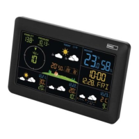
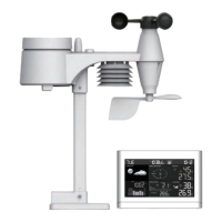
Weather Station Description
Front Screen – Icons
(see Fig. 1)
1 – sensor batteries low
2 – outdoor temperature
3 – wireless communication with sensor
4 – pressure trend indicator
5 – SNOOZE/LIGHT button
6 – weather forecast
7 – pressure history chart
8 – station batteries low
9 – indoor temperature
10 – temperature index
11 – indoor humidity
12 – moon phases
13 – moonrise and moonset time
14 – city name abbreviation
15 – sunrise and sunset time
16 – alarm no. 1, no. 2
17 – date, day name
18 – time
19 – DCF signal reception / DST – daylight
savings time
20 – pressure history
21 – relative / absolute pressure value
22 – outdoor temperature trend indicator
23 – outdoor sensor channel number
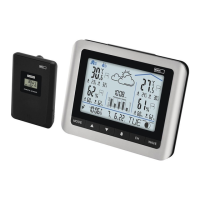
Back of the Weather Station
(see Fig. 2)
24 – +/12/24 h time format button
25 – Relative/Absolute button
26 –
button
27 – MAX/MIN/- button
28 – MODE button
29 – °C/°F/+ button
30 – ALARM/ON/OFF button
31 – HISTORY/WEATHER button
32 – SUN/MOON button
33 – CHANNEL button
34 – holes for hanging
35 – RESET button
36 – acoustic signalisation
37 – battery compartment
38 – stand
Sensor Description
(see Fig. 3)
39 – °C/°F button
40 – TX button
41 – hole for hanging
42 – sensor channel number 1/2/3 setting
43 – battery compartment
44 – stand