3
• The unit can be located anywhere you want to control temperature, irrespective of the switched
system location, not limited by a connection cable.
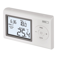
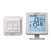
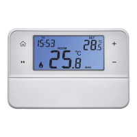
• Large multi-purpose LCD display with electronic backlight
• User-friendly temperature setting an programming
• 6 factory pre-set programs, 3 user-dened programs
• Anti-frost protection
• Temporary change option by set temperature program
• User programmable variance of set temperature.
• User dened control of heating/cooling mode
• Sleek design of the thermostat for easy installation on the wall
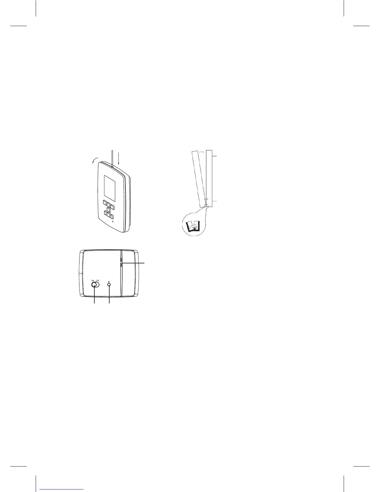
How to remove rear cover of the control unit
1. Use a screwdriver to press and hold the inner lock.
2. Remove front cover.
remove
front cover
front part rear part
use a screwdriver
to press and hold
the inner lock
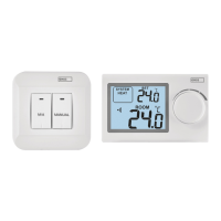
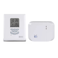
Switching unit
LED indicators
main switch pairing button
LED indicators
• Blue LED indicates the switching unit is powered from 230 V AC. If the unit is not connected to
the mains, or if the main switch is in the OFF position, the blue LED is not lit.
• Red LED is lit when the heating/air-conditioning system is powered.
Main switch
We recommend switching o the switching unit if the heating/air-conditioning system is not used
(main switch to the OFF position).
Installation
Pairing of the control unit with the switching unit
Pairing enables transfer of information between the control unit and switching unit.
It is set by auto-pairing (self-learning) mode using the ID button.
1. Insert 2× 1.5 V AA batteries into the control unit (make sure polarity of the batteries is correct).
Only use alkaline batteries, not rechargeable ones.
2. Connect the switching unit correctly to the power source, and press and hold the ID button;
the upper red LED starts ashing.