5
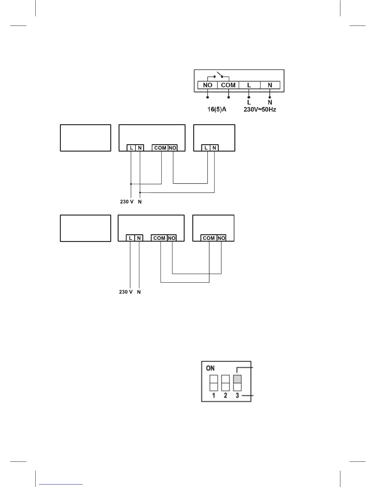
Wiring Diagram
The T15RF thermostat can be used with any one-stage heating or air-conditioning system.
NO switched contact
COM switch contact
L connection of power 230 V AC
N neutral wire
Wiring diagram for 230 V AC/50 Hz
control
unit
switching unit
heating
system
Wiring diagram for potential-free switching
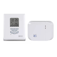
control
unit
switching unit
heating
system
Installation of control unit (if you do not wish to use the unit’s mobility)
1. Remove the control unit rear cover.
2. Mark positions of the holes for rear cover.
3. Drill two holes, carefully insert plastic dowels ushing them with the wall.
4. Use two screws to attach rear cover of the control unit.
5. Complete the installation by mounting the switching unit to the attached rear part of the cover.
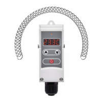
Selecting heating/air-conditioning system
1. Remove the rear cover of the control unit - PCB
holds 3 DIP switches. These 3 switches are used
to adjust the variance of temperature and toggle
between heating/air conditioning system.
2. Set the DIP switch (position 3) depending on your
choice of heating or air conditioning system, as
shown in the following gure.
ON – heating
OFF – air-conditioning
Switch No. 3