Emotron AB 01-3991-11r2 Kabeldragning 141
Plintblock, styrsignaler
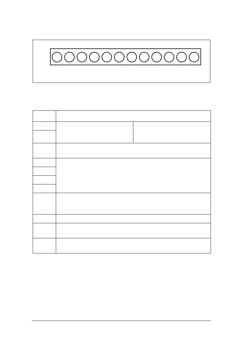
Fig. 32 Styrsignalplintarnas placering
Tabell 64
Symbol Beskrivning
RA
Flerfunktionsutgångsplint Bry-
tande kontakt
Märkbrytförmåga: (250 VAC/10 A).
Kontaktbeskrivning: (se meny
[551])
RB
24 V
PNP-ingång (SOURCE), S1 till S4 (S5/S6/S7) gemensam plint, (sätt
SW1 till PNP och anslut strömförsörjning till optionskort).
S1
Flerfunktionsingångsplintar (se beskrivning av [521] till [524])
S2
S3
S4
COM
NPN-ingång (SINK), S1 till S4 (S5/S6) gemensam plint, (sätt SW1 till
NPN, och analog ingång, anslut strömförsörjning till optionskortet,
utsignal till gemensam plint).
10 V Strömförsörjning för extern potentiometer för varvtalsreferens.
AIN
Analog ingångsplint för frekvenssignal eller flerfunktionsingångsplint
S7 (hög: 8 V/låg: 2 V), inställbar för PNP (se beskrivning av [511])
FM+
Analog flerfunktionsutgång + plint (se beskrivning av [531]), utsignal:
0–10 VDC.
123456789101112
TM2
RA
RB
24 V
S1
S2
S3
S4
COM
10 V
AIN
COM
FM+
 Loading...