40 Wiring notes Emotron AB 01-3991-11r2
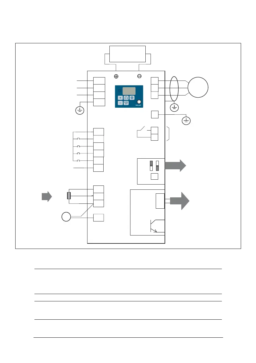
VSA wiring diagram
Fig. 9 Wiring diagram
NOTE: Connect inputs to terminal 3 (internal 24 VDC) for PNP mode
(Positive switching), or to terminal 8 (common) for NPN mode (negative
switching).
NOTE: External 24 VDC may be used to supply the external contacts at each
input (connect the 0 V of the external supply to common (terminal 8)).
L1
L3(N)
L1(L)
L2*
PE
24V
S1
S2
T1
T2
T3
RB
RA
21
COM
10V
AIN
COM
FM+
S4
S3
PE
FM
IM
S5
S6
Power terminal
1 phase 200 to 240 V
3 phase 380 to 480 V
PNP common point
Multi function digital
Accept DC 12/24V
NPN common point
Multi-function
Set speed
PID feed back
10k
Multi-function digital output
1. SW1: Digital signal
2. SW2: Control signal
Option interface
Multi-function on output
Remote keypad
24 V/0.6 A
input card (2IN/1OUT)
selection (0–10 V/4–
Braking
unit
selection (NPN/PNP)
inputs
signal
analogue input
input
20 mA) V/I
(1)
(2)
T+
T-
(3)
(4)
(5)
(6)
(7)
(8)
(9)
(10)
(11)
(12)
 Loading...