Emotron AB 01-3991-11r2 Wiring notes 41
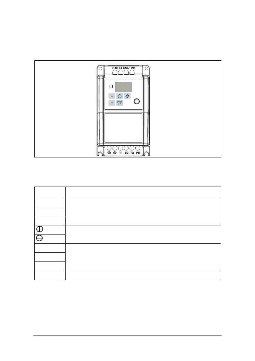
Description of VSD Terminal
Descriptions of power terminals
Fig. 10 Power terminals locations
* Braking units are required for applications where a load with high inertia
needs to be stopped rapidly. Use a power-matched braking unit and resistor to
dissipate the energy generated by the load while stopping. Otherwise VSD will
trip on over voltage.
* Terminal at L2 will be non-functional for single-phase units.
Ta bl e 1 8
Symbol Description
L1 (L)
Main power input Single-phase: L/N* Three-phase: L1/L2/L3L2
L3 (N)
DC power and braking unit connection terminals. (match with brak-
ing units and braking resistor to brake)
T1
VSD outputT2
T3
PE Grounding terminals (2 points)
 Loading...