Emotron AB 01-3990-11r3 Índice del software 95
Índice del software
Instrucciones de uso del teclado
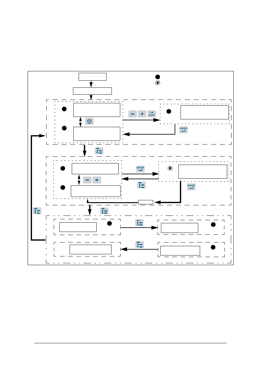
Figura 20
*1: Después del encendido, en el VSD parpadeará el ajuste actual de 0-07
(tensión de alimentación).
*2: 4-04 y 4-05 determinan si se mostrará la frecuencia, la velocidad o la
velocidad de línea.
*3: No es necesario pulsar la tecla Enter cuando se para para una modificación.
Consulte los ejemplos 1 y 2.
*4: 4-00 a 4-03 determinan si se muestra o no la intensidad de salida, la tensión
de salida, la tensión CC o el estado del PLC integrado.
FUN
FUN
Seleccionando el juego
Seleccionando el
Frecuencia/Velocidad/
Velocidad de línea (ajuste)
FUN
Alimentación
Tensión (*1)
Hz/RPM
Hz/RPM
Frecuencia/Velocidad/
Frecuencia/Velocidad/
Frecuencia/Velocidad/
Hz/RPM
END
Tensión de salida
Estado PLC integrado
Tensión CC
VOLTIOS
VOLTIOS
AMPERIOS
(*3)
(*2)
(*4)
5 segundos después: introducir la señal de funcionamiento o
Indicador LED encendido
Indicador LED intermitente
pulsar DSP para modificar la frecuencia
Velocidad de línea (ajuste)
Velocidad de línea (paro)
Velocidad de línea
de parámetros
0-00
juego de parámetros 10-0
Intensidad de salida
 Loading...