Emotron AB 01-3990-11r3 Software index 57
Software index
Operating Instructions for the keypad
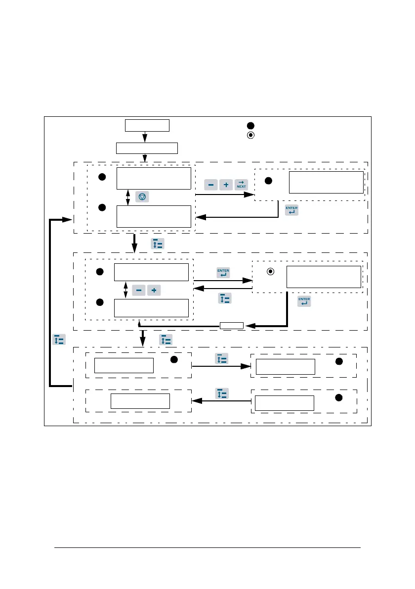
Fig. 13
*1: The VSD will flash the current setting of 0-07 (power supply voltage) after
power up.
*2: 4-04, 4-05 determines the displaying of frequency, speed or line speed.
*3: It is not necessary to press the Enter key when stopped for modification.
Refer to example 1 and 2.
*4: Whether or not output current, output voltage, DC voltage, or status of built-in
PLC is displayed is determined by 4-00 to 4-03 respectively.
FUN
FUN
Selecting the
parameter group 0-00
Selecting the
parameter group 10-0
Frequency/Speed/
Line Speed (In setting)
FUN
Power On
Power voltage (*1)
Hz/RPM
Hz/RPM
Frequency/Speed/
Line Speed (stop)
Frequency/Speed/
Line Speed
Frequency/Speed/
Line Speed (In setting)
Hz/RPM
END
Output Voltage
Built-in PLC Status
DC Voltage
Output Current
VOLT
VOLT
AMP
(*3)
(*2)
(*4)
5 seconds later or Enter operation signal or Press DSP to modify frequency
LED Light lit
LED Light flashing
 Loading...