2. Sensor mounting
Depending on the application, a motor position sensor
may be required. EMRAX offers a variety of different
positioning sensors that can be supplied together with
the motor. This chapter will cover their installation.
2.1. RLS RM44 encoder installation
Required parts:
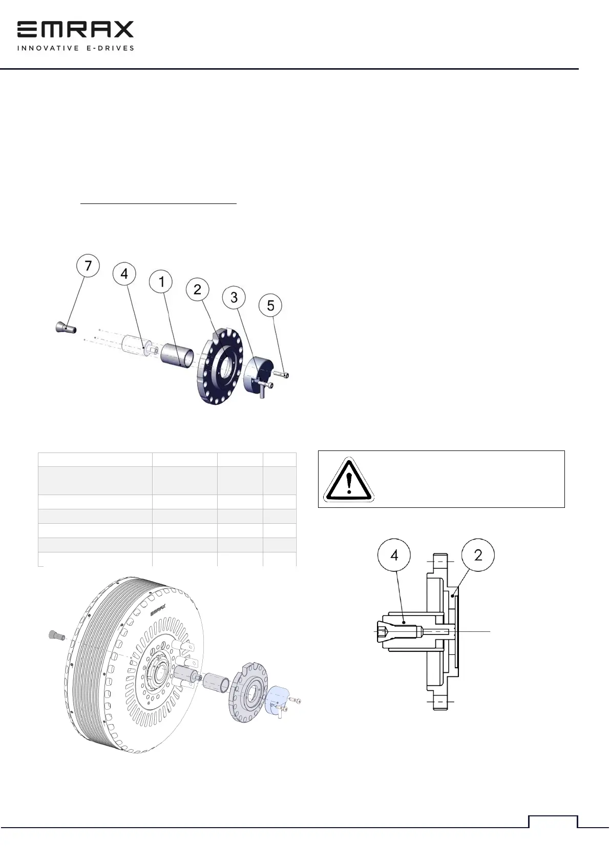
Figure 1: Required mounting parts
Figure 2: Encoder assembly
1. Place an adapter (1) inside the motor shaft
(this step is only required for the 268 and 348
motor types). Before inserting the part use
threadlocker glue on the faces, where the
parts are mated.
2. Insert the tapered bolt (7) into the encoder
magnet set (4) and lightly tighten it. Using
threadlocker glue supplied with the kit on the
threads is recommended.
3. Insert the encoder magnet set (4) into the
backside of the motor (as shown on Figure 2),
inside the motor shaft. Before inserting the
part use threadlocker glue on the faces, where
the parts are mated.
4. Mount the encoder bracket (2) on the back of
the motor (as shown on Figure 2). Make sure
that it is seated in its position, if necessary,
use temporary bolts to tighten it to the motor
(If the motor is liquid or combined cooled,
please make sure that the coolant fittings are
inserted, before mounting the encoder
bracket, please refer to 3.5).
5. Align the encoder magnet set (4) to the
sensor mounting flange of the encoder
bracket (2).
Use an object with a flat face and make
sure that the encoder magnet and the
mounting face of the bracket are perfectly
colinearly (in same line) aligned.