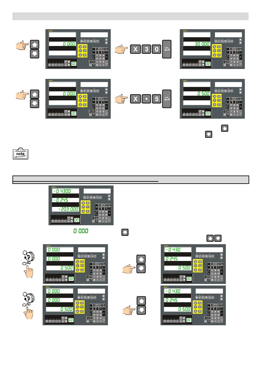
Navigate to the plane Angle entry and enter the required value.
INCL ANG
INCL ANG
Inclined Machining: Continued…
Navigate to the Max Cut entry and enter the required value.
MAX CUT
MAX CUT
Once all the parameters have been entered you can check them by going back through them using the
navigation key . Alternatively you can also start using the function immediately by pressing the key once more.
The message window will show the first machining Point
with the X & Y-axis displays left aligned to indicate that it
is operating in a special mode.
PT 1
Move the X-axis and Y-axis to . . Then press the key to move to the next next point and repeat the process
until the ARC machining operation is completed. You can navigate through the points using the keys
PT 1
PT 2
PT 2
PT 3
The following is only required for the XY Plane. (2-axis and 3-axis DRO)
The execution of the function varies between 2-axes and 3-axes DRO for the YZ & XZ planes as we have to
use the Z-dial calibration performed in Setup to simulate the Z-axis on 2-axes DRO systems.
- 26 -
 Loading...