Do you have a question about the Emtron DX-1d and is the answer not in the manual?
Identifies and illustrates the main internal components of the Emtron DX-1d amplifier.
Guidance on how to open the product packaging without causing damage.
Steps for removing the amplifier's top cover to inspect internal components.
Instructions on how to remove internal foam packaging and check the tube seating.
Details the necessary conditions for installing the amplifier, including temperature and air quality.
Outlines the AC power specifications and current draw needed for operating the amplifier.
Details the procedures for making safe power supply and ground connections to the unit.
Explains how to connect the RF input and output using coaxial cables.
Covers ALC and PTT connections for integrating with a transceiver or exciter.
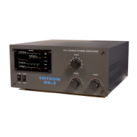
Describes the BAND SWITCH, PLATE TUNE, LOAD TUNE, ON/OFF, and OPR/STBY controls.
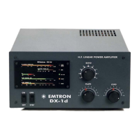
Explains the various LED and analog meter indicators on the front panel.
Outlines signal and control connections between the DX-1d and a transceiver or exciter.
Details the correct procedures for establishing earth and AC mains power connections.
Information regarding power cables supplied with export versions of the amplifier.
Instructions for configuring the amplifier for different mains voltage inputs.
Describes the RF section, including tuned circuits, tank coils, and the RF sub-chassis.
Explains the function and specifications of the amplifier's high-performance mains transformer.
Details the high voltage DC power supply circuitry, including rectifier and filter components.
Explains the soft start circuitry that manages initial power application to avoid surge currents.
Describes the sensor module responsible for detecting forward and reverse power.
Details the antenna relay and optional QSK module for transmit/receive switching.
Describes the central controller board and its various regulated circuits.
Detailed guide on how to tune the amplifier for optimal performance on different bands.
Steps to diagnose and fix issues where the amplifier does not power on.
Procedures for addressing problems related to the amplifier's cooling fan.
Explains the causes and solutions when the FAULT indicator light is illuminated.
Information on the over-temperature protection mechanism and its operation.
Troubleshooting guide for when the Ig2 display indicates issues related to plate voltage.
Addresses potential issues caused by sparks or discharges within the RF section.
Explains the protection triggered by high Standing Wave Ratio (SWR) and its bypass function.
Information on resolving frequent activation of the over-drive protection system.
Guidance on replacing the amplifier's vacuum tube and required adjustments.
A high-level block diagram showing the interconnections of major amplifier modules.
Detailed circuit diagram for the amplifier's high voltage power supply section.
Illustrates the control board, showing connections and points for adjustment.
Schematic detailing the AC input and wiring for the standard version.
Schematic detailing the AC input and wiring for the U.S. version.
Circuit diagram for the soft start module used in 200-240V operation.
Circuit diagram for the optional QSK module, illustrating its functionality.
Detailed circuit diagram of the RF module, including the vacuum tube stage.
Comprehensive circuit diagram for the amplifier's control board.
Identifies components on the control board using silkscreen markings.
Illustrates the solder side track layout of the amplifier's control board.
Displays a waveform showing the switching sequence of the optional QSK module.
Shows a sample linearity curve obtained from the amplifier under test conditions.
Guides on performing essential adjustments on the amplifier's control board.
Instructions for adjusting the SWR protection threshold using specific test equipment.
Procedure for adjusting the Electronic Bias Switch (EBS) sensitivity and activation point.
Details how to adjust the screen grid voltage to its nominal value.
Instructions for adjusting the screen current limit to protect the tube.
Guides on adjusting the high plate current trip sensitivity for protection.
Procedures for fine-tuning the amplifier's display board indicators for accurate readings.
Instructions for adjusting the RF sensors for accurate forward and reflected power measurements.