EasyManua.ls Logo

Emtron DX-3 User Manual

Default Icon
42 pages
To Next Page IconTo Next Page
Page #1 background imageLoading...
Page #1 background image
OPERATING MANUAL
EMTRON DX-3
HF LINEAR AMPLIFIER
April 2005
Emtron
DIVISION OF EMONA ELECTRONICS PTY. LTD.
92-94 Wentworth Avenue, Sydney 2010, Australia
Tel. +612 92110988 Fax +612 92811508
www.emtron.com.au

Table of Contents

Question and Answer IconNeed help?

Do you have a question about the Emtron DX-3 and is the answer not in the manual?

Emtron DX-3 Specifications

General IconGeneral
BrandEmtron
ModelDX-3
CategoryAmplifier
LanguageEnglish

Summary

GENERAL DESCRIPTION

DX-3 Internal View

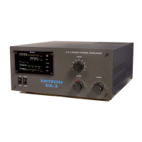
Overview of the amplifier's main components and layout.

TECHNICAL SPECIFICATIONS

UNPACKING PROCEDURES

Transformer Installation

Instructions for physically installing the power transformer into the amplifier chassis.

INSTALLATION ENVIRONMENT GUIDELINES

Power Requirements

Details on the electrical power supply needs and ratings for the amplifier.

REAR PANEL CONNECTIVITY

Transceiver Control Interfaces

Connectors for controlling transmit/receive and ALC signals.

FRONT PANEL OPERATION

Front Panel Displays and Indicators

Explanation of the LED indicators and power/current readings.

ELECTRICAL CONNECTIONS

Transceiver and Antenna Connections

Guidance on connecting the amplifier to a transceiver and antenna.

DX-3 SYSTEM DESCRIPTION

RF Section Overview

Description of the RF components, tuning circuits, and tube housing.

POWERING UP THE AMPLIFIER

OPERATION AND TUNING

Tuning Procedure Guide

Step-by-step instructions for tuning the amplifier for optimal performance.

ALC ADJUSTMENT PROCEDURE

TROUBLESHOOTING COMMON ISSUES

Fault Light Indications

Explains the meaning of various fault lights and their causes.

WARRANTY AND SERVICE INFORMATION

GLOSSARY OF TERMS

APPENDIX 1: SCHEMATIC DIAGRAMS

DX-3 Block Diagram

High-level block diagram illustrating the main functional modules of the DX-3.

High Voltage Power Supply Schematic

Schematic detailing the high voltage power supply circuit.

Control Board and Adjustment Points

Diagram showing control board connections and potential adjustment points.

APPENDIX 2: WAVEFORMS

Linearity Waveform Analysis

Visual representation of amplifier linearity under test conditions.

APPENDIX 3: ADJUSTMENTS

Control Board Adjustments

Detailed procedures for adjusting various parameters on the control board.

Display Board Adjustments

Procedures for fine-tuning the display board readings.

RF Sensor Adjustment

Calibration procedure for the RF sensor module.

Related product manuals