40
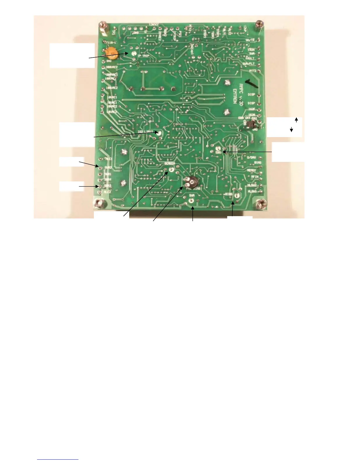
Figure 7
17.2 DISPLAY BOARD ADJUSTMENTS
The display board is pre-adjusted during testing. However, when installed in the amplifier, most adjustments need to be fine-tuned.
Remove the front panel glass to gain access to adjustments.
17.2.1 PLATE CURRENT (Adjustment: VR4, Marked: AMP)
Connect a power supply to pin TP2 on the control board: negative to TP2, positive to the chassis.
Apply a current with a value between 1 A and 2 A. Choose a convenient value close to the full scale on the Ip LED row on
the display board.
Adjust potentiometer AMP for correct indication.
17.2.2 PLATE VOLTATE (Adjustment: VR2, marked: VOLT)
Using a voltmeter with a high voltage probe, measure the plate voltage.
Adjust potentiometer VOLT for correct indication on the display.
17.2.3 REFLECTED POWER (Adjustment: VR3, marked: RF R)
Reverse the input and output RF connections:
- connect the transceiver or exciter to the output
- connect the dummy load to the input of the amplifier
Apply 100W drive and adjust “RF R” for 100W indication
Reverse again the RF cable - connect them the right way.
BIAS
(Ip0)
PRE-BIAS SWR
SCREEN
VOLTAGE
EBS
SENSITIVITY
EBS OFF
EBS ON
SCREEN
CURRENT
LIMIT
PLATE
CURRENT
PROTECTION
SWR1
SWR4