EMX Industries, Inc. Tech support: 216-518-9889 2/6
IRB-MON_Rev3.3_072720 technical@emxinc.com
UL325 requires continuous monitoring of all safety devices connected to gate and door operators.
Consult the gate or door operator manufacturer’s instruction manual for necessary monitoring
method.
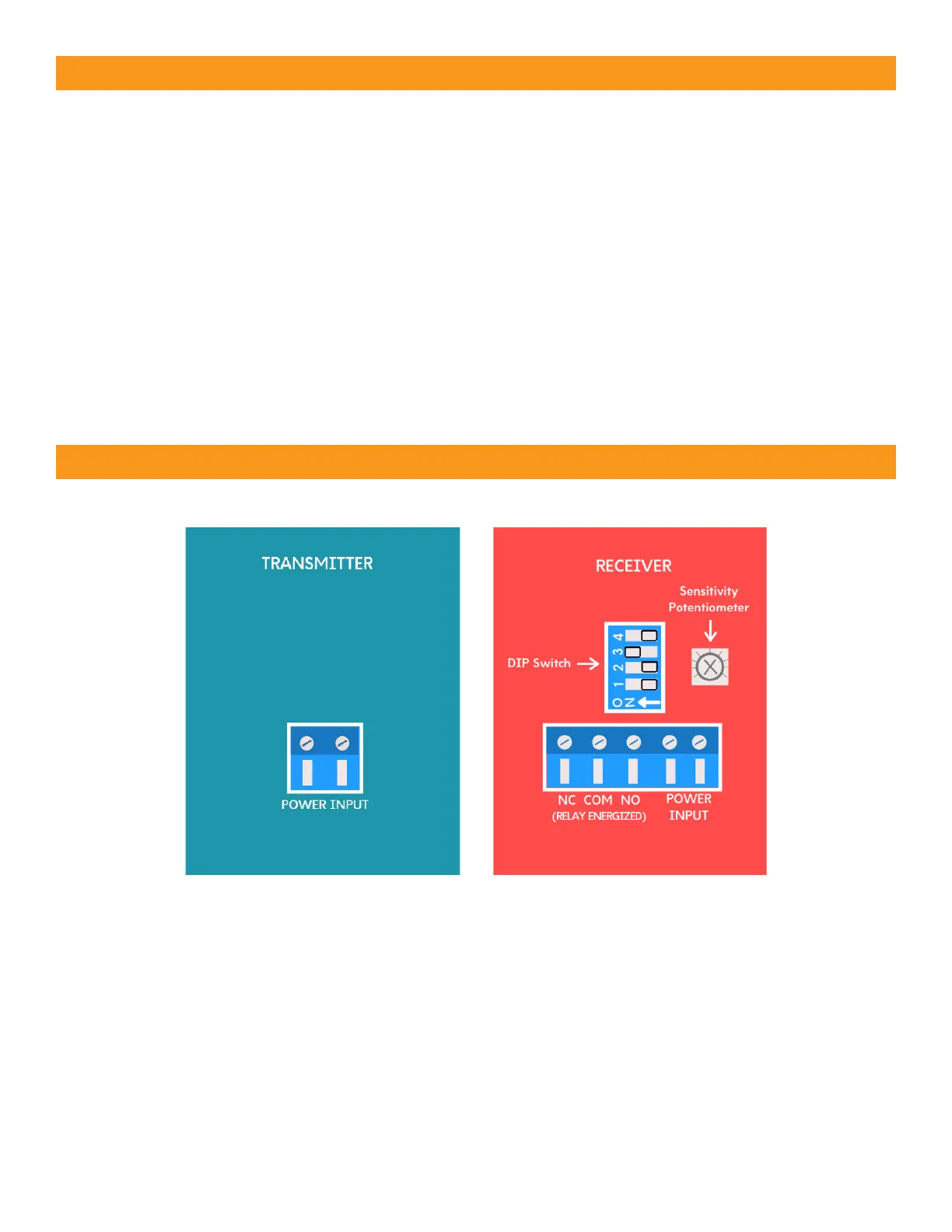
• Normally Closed (Wiring Diagram A): The operator cycles power to the transmitter while monitoring
the receiver N.C. (Normally closed) contacts for proper operation
• 10K Resistive Termination (Wiring Diagram B): Provides a measurable 10K ohm resistance across
the N.O. (normally open) relay when unobstructed and in Fail Safe mode
• Two-Wire Pulse, 2 Frequency (Wiring Diagram C): Provides 300Hz “heartbeat” unobstructed,
0Hz obstructed over the receiver input power supply lines
• Two-Wire Pulse, 3 Frequency (Wiring Diagram D): Provides 300Hz “heartbeat” unobstructed,
2Hz obstructed, and 0Hz when failure is detected, over the receiver input power supply lines